Do you have a question about the AERMEC NLC 0350 and is the answer not in the manual?
Precautions for hydraulic, electrical, and cooling circuits.
Safety advice on refrigerants and requirements for connecting to hydronic systems.
Presents refrigerant circuit diagrams for NLC 0280-0675 A and NLC 0750-1250 A models.
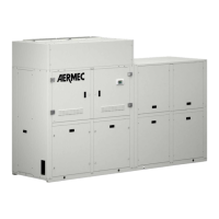
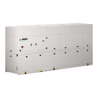
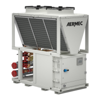
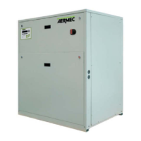
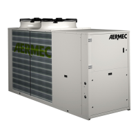
Criteria for selecting installation location and unit positioning guidelines.
Specifies required clearances around the unit for maintenance and airflow.
Presents hydraulic circuit diagrams for different NLC models and configurations.
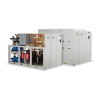
Provides electrical data, wiring instructions, and power connection details.
Steps for unit start-up, pre-checks, hydraulic checks, and operational checks.
Safety precautions, routine maintenance, compressor replacement, and decommissioning guidelines.