14 - EN
EN
NLC_A cod: 1606.4037360_00
A
B
C
E
I
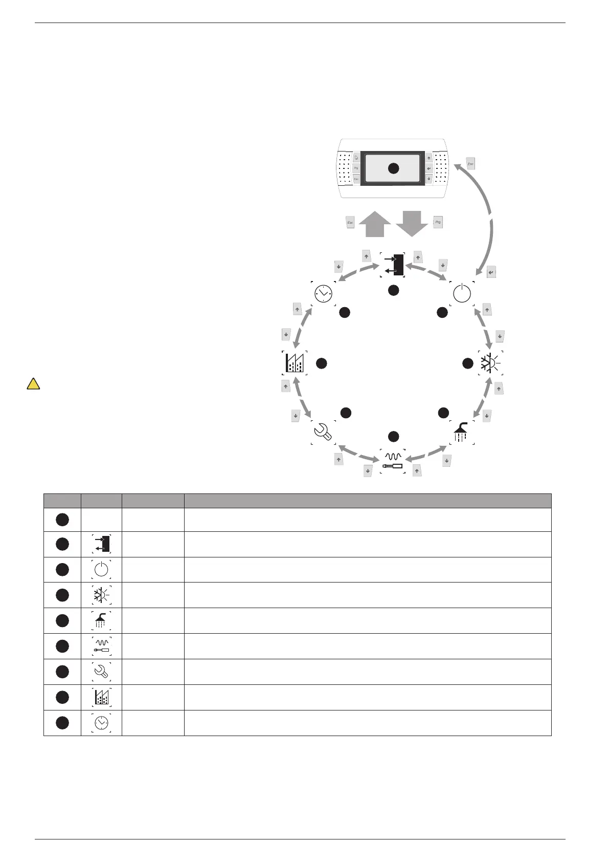
Both the func ons to control the unit and the opera ng informa on
are displayed on the unit mounted control panel. All the func ons
and informa on are arranged in screens which in turn are grouped
into menus.
During the normal opera on of the unit the main screen is displayed,
from which it is possible to access the selec on of the other opera ng
menus.
The menus are displayed through the rota on of the icons that they
represent. Once the desired icon is selected the chosen menu is en-
tered, permi ng the display or modifi ca on of the parameters that it
is made up from. The procedure for naviga ng the menus, or chang-
ing parameters, is explained in detail in the chapter “User opera ng
procedures”.
The adjacent drawing shows the rela on between the various menus
and the naviga on keys used.
A
--- MAIN The screens in this menu display the current conditions of the unit (unit status, setpoints,circuit data, etc.)
B
IN/OUT This menu contains advanced information on the unit operation
C
ON/OFF This menu permits the unit to be enabled or disabled, and provides information on the status
SYSTEM This menu permits the selection of the operating modes, the water setpoints and the time-clock for the system
E
RECOVERY If the unit includes heat recovery, this menu permits the setting of the parameters associated with the heat recovery
INSTALLER
This menu contains the settings useful for the installer (enabling digital inputs, BMS configuration, control, pumps, etc.)
ASSISTANCE This menu is only accessible to qualified personnel
FACTORY This menu is only accessible to qualified personnel
I
CLOCK This menu contains the clock settings for the system control (date, hour, calender)