Do you have a question about the AERMEC NRW Series and is the answer not in the manual?
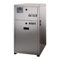
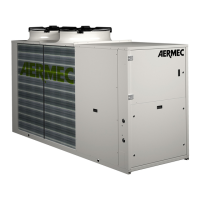
General overview of the NRW series chillers and heat pumps.
Details available model sizes and version codes.
Lists and illustrates the main physical components of the units.
Provides detailed technical descriptions for each numbered component.
Details components 16, 17, 18.
Discusses the microprocessor card and its functions.
Explains compressor, pump, and reversing valve management.
Lists safety interlocks, circuit breakers, and switches.
Details the PGS, PR, and VP accessories.
Shows compatibility between NRW models and various accessories.
Provides technical specifications for R22 models, including capacity and power.
Provides technical data for R22 E models, covering capacity and power.
Provides technical data for R407C models, including capacity and power.
Provides technical data for R407C E models, covering capacity and power.
Warns against incorrect applications and unsafe practices.
Explains important safety symbols used in the manual.
Guides on how to select the appropriate unit based on project requirements.
Demonstrates the unit selection process with a practical example.
Illustrates the operational limits of the units based on temperatures.
Shows pressure drops for the external heat exchanger circuit.
Shows pressure drops for the installation circuit heat exchangers.
Displays effective pressure for the user circuit (NRW 2-4).
Displays effective pressure for the user circuit (NRW 3-4).
Displays effective pressure for the user circuit (NRW 4-47).
Illustrates pressure drops for the water filter based on flow rate.
Provides correction factors for evaporator/condenser At variations.
Provides correction factors based on fouling factor.
Lists sound pressure and power levels for various models and frequencies.
Shows the adjustable range for control parameters like temperature and autostart.
Details the settings for protection devices like pressure switches.
Provides correction factors for glycol/water solutions at different temperatures.
Lists specifications for refrigerant line lengths and diameters.
Provides instructions for lifting and positioning the unit safely.
Specifies requirements for indoor installation and clearance.
Details hydraulic connections, filter placement, and recommended accessories.
Emphasizes mandatory water filter installation for warranty.
Covers factory wiring, power supply, and local regulations.
Lists checks required before powering on the unit.
Refers to the manual for functional parameter settings and detailed operation.
Explains procedures to prevent freezing damage during winter shutdown.
Explains the function of dip switches for unit configuration.
Provides overall dimensions and hydraulic connection details for NRW 2-47.
Details hydraulic line sizes for NRW-E models.
Provides overall dimensions and hydraulic connection details for NRW 5-127.
Lists refrigerant line sizes for NRW-E models.
Illustrates required clearance around NRW 2-47 units.
Illustrates required clearance around NRW 5-127 units.
Shows dimensions of the remote control panel accessory.
Provides dimensions for the VT anti-vibration pads.
Defines symbols used in the refrigerant circuit diagrams.
Shows the refrigerant circuit layout for NRW 2-47 models.
Shows refrigerant circuit layout for NRW 2E-47E models.
Shows refrigerant circuit layout for NRW 2H-47H models.
Shows refrigerant circuit layout for NRW 5-127 models.
Shows refrigerant circuit layout for NRW 5E-127E models.
Shows refrigerant circuit layout for NRW 5H-127H models.
Defines symbols used in the electrical wiring diagrams.
Provides electrical data (cable sizes, current ratings) for different models.
Shows the power connection wiring diagram for NRW 2-47 (230V).
Shows the power connection wiring diagram for NRW 3-47 (400V).
Shows the power connection wiring diagram for NRW 5-127 models.
Wiring diagram for control panel and safeties of NRW 2-47 units.
Wiring diagram for control panel and safeties of NRW 2H-47H units.
Wiring diagram for control panel and safeties of NRW 5-127 units.
Wiring diagram for control panel and safeties of NRW 5H-127H units.
Wiring diagram for control panel and safeties of NRW 10-107 units.
Wiring diagram for control panel and safeties of NRW 10H-107H units.
Wiring diagram for control panel and safeties of NRW 2E-27E units.
Wiring diagram for control panel and safeties of NRW 3E-47E units.
Wiring diagram for control panel and safeties of NRW 5E-127E units.
Wiring diagram for control panel and safeties of NRW 10E-107E units.