25
IHLPCLJ 1809 - 6887206_04
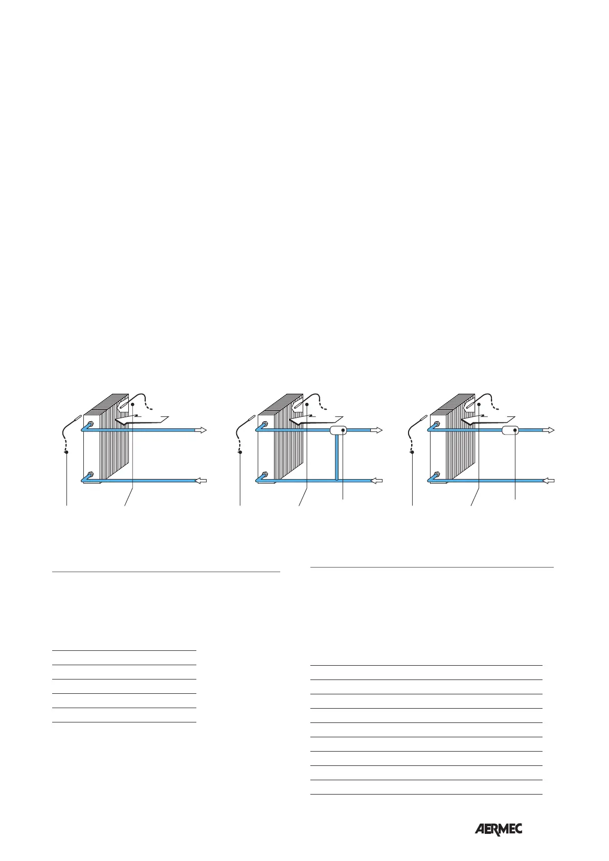
SYSTEM EXAMPLES
SA
AIR
SA
AIR
SWSW
VCH
SA
AIR
SW
VCH
SW Water temperature sensor
VCH Solenoid valve (Heating / Cooling)
SA Room temperature probe
Key:
OPERATING ENVIRONMENT
The units are designed for installaon in closed environments in condions
of ‘urban’, non-marine atmosphere with non-corrosive and non-dusty
characteriscs.
Under no circumstances the following concentraons of pollutants in the air,
in which the unit must operate, shall be exceeded:
SO
2
<0,02 ppm
H
2
S <0,02 ppm
NO,NO
2
<1 ppm
NH
3
<6 ppm
N
2
O <0,25 ppm
The unit should not be installed in locaons characterized by the presence of
ammable gases or acidic or alkaline substances.
Otherwise the coils and the internal components of the equipment could
suer serious and irreparable damage from corrosi
WARNINGS FOR THE QUALITY OF THE WATER CIRCULATING
IN THE COILS
It is recommended to perform an analysis of the water circulang in the coil
focusing on the research of the possible presence of bacteria (detecon of
iron bacteria and micro-organisms that can produce H2S or chemically reduce
sulphates) and on the chemical composion of the water, to prevent corrosion
and fouling inside the tubes.
The water circuit must be supplied and replenished with treated water that does
not exceed the threshold levels indicated below.
Total hardness in mmol/l l < mmoll/l < 1,5
Chlorides [CL
-
] < 10 mg/litre
Sulphates [SO
4
2-
] < 30 mg/litre
Nitrates [NO
3
-
] = 0 mg/litre
Dissolved iron < 0,5 mg/litre
Dissolved oxygen 4 < [O
2
] < 9 mg/litre
Carbon dioxide [CO
2
] < 30 mg/litre
Resisvity 20 Ohm∙m < Resisvity< 50 Ohm∙m
pH 6,9 < pH < 8
C in winter mode,
- 22 ° C to 25 ° C or Normal Cold Cold
Reduced, (can be configured via a DIP
switch).
Water temperature controls
The thermostat enables the ventilation
only if the water temperature is suit-
able to the way Warm or Cold.
The thresholds enable ventilation are:
- 39 ° C in normal winter mode or 35 °
C in winter mode,
- 17 ° C or 22 ° C Normal Cold Cold
Reduced,
(Can be configured via a DIP switch).
The control panel indicates the situation
in which the water temperature is not
appropriate to the operation mode set,
via the alternate flashing on the LED C
of fuchsia color with red or blue colors
related to the active mode.
Correcting probe
You can select a correction to apply to
the sensor.
Frost Protection (frost protection)
Frost protection plan to check that the
temperature never drops in values of
frost, even when the fan is switched off
and the selector (A) is OFF.
In the case where the temperature drops
below 7 ° C, the thermostat starts the
fan coil in the hot operation with set
at 12 ° C and ventilation in AUTO, if
the temperature of the water so allows,
that the fan coil unit is powered on
and that, for models with manual flap,
the flap outlet is in the open position.
It leaves the way frost when the tem-
perature rises above 9 ° C.
Emergency mode
In case of failure of the electronic ther-
mostat probes it behaves in the follow-
ing way:
- Ambient probe SA fault, the thermostat
enters “Emergency”, indicated by the
flashing of the LED (D) yellow.
With selector (A) in the OFF position the
fan is switched off.
With selector (A) in AUTO, V1, V2 and
V3 fan run cycles on - off; in this situ-
ation the power delivered by the ter-
minal is controlled manually via the
temperature selector (B), turning to the
right the cycle duration of Lit increas-
es; turning to the left decreases the
time.
- Failure SW water probe, the ther-
mostat enters “Change season from
September.”
The ventilation is always enabled.
The season change takes place accord-
ing to the following rules:
a) if the thermostat is in cooling mode
and the demand of the thermostat is 5
° C below the set point, then automati-
cally the thermostat requires heating
mode.
b) if the thermostat is in heating mode
and the demand of the thermostat is
5 ° C above the set point, then the
thermostat automatically requires the
cooling mode.


 To Next Page
 Loading...