User Manual - URX_CF and URHE_CF -
5
Main features
General
The unit is tted with an electrical panel with
a power and regulation section (including the
three-way valves for the integrated hot water
coil, if present, and the related servomotors), for
the control of all cooling circuit functions. The
following is included: NTC temperature probe on
the ambient air intake, outside air NTC temper
-
ature probe, pressure switch on the intake lter.
With the free cooling accessory, the dampers and
related servomotors are provided. A remote con
-
trol terminal is also provided for the automatic
control of the unit, with remote control up to 100
metres (cable not provided).
The main functions of the regulation sys-
tem are as follows:
• thermo-regulation depending on the
temperature detected by the air probe
located on the recovery;
• defrosting control;
• remote ON-OFF;
• summer/winter switching
• integrated electric coil control for heat-
ing (if present);
• integrated water coil control for heating
(if present);
• menu user interface;
• remote keyboard (up to 100 m) that
can be directly connected without serial
interfaces (electrical cable not provided);
• RS485 serial board with series ModBus
protocol.
Diagnostics
The regulation system includes the notifi-
cation of the following faults:
• defective temperature probe
• cooling circuit high and low pressure
• compressor thermal protection
• fan thermal protection
Remote keyboard assembly
The connection between the control
board of the remote keyboard and con-
trol board of the electrical panel takes
place through electrical cables that are
not provided (shielded cables with a sec-
tion of at least 0.5 mm
2,
, max. length 100
m).
For the connection to the clamps, refer to
the section “Remote keyboard connec-
tion”.
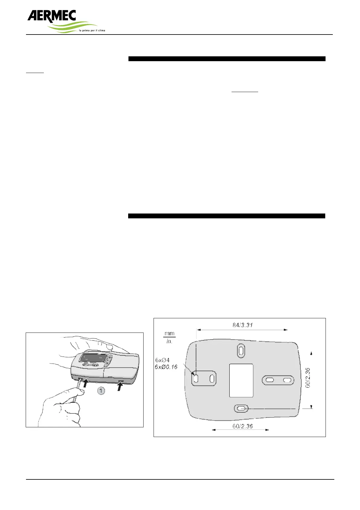
Access to the keyboard control board
takes place by remove the front part (by
means of a screwdriver or similar tool) as
fig. 01 shows.
The cables can pass through the central
hole A in the rear part of the remote key-
board (fig. 02).
For the wall installation, after removing
the front part, on the wall where the key-
board is going to be installed, make no.
4 holes with 4 mm diameter with the
correct distance (see diagram in fig. 02).
After preparing the connections, close
back the front part of the keyboard by
simply pressing with your fingers.
Fig.1
Fig.2
H