User Manual - URX_CF and URHE_CF -
6
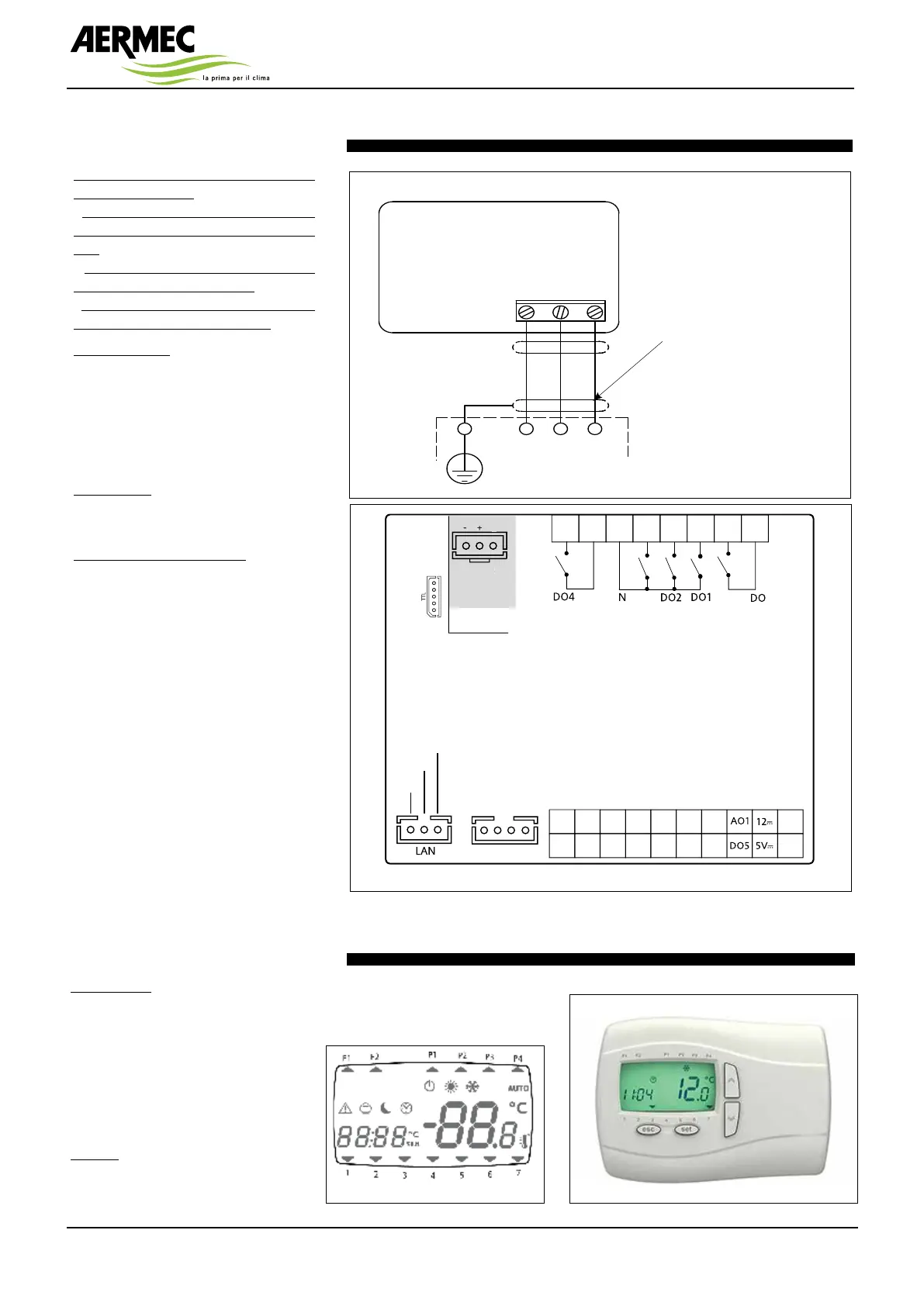
Remote keyboard connection
The following rules must be followed when
doing the connections:
- do not apply loads greater than the ones
included in these specifications on the out
-
puts;
- when connecting the loads, carefully
observe the connection diagrams;
- keep the power cables separated from the
signal cables to prevent interferences.
Analogue inputs
The analogue inputs are 5:
• 3 inputs for the NTC temperature
probes;
• 1 configurable input for NTC probe or
for signal 4...20 mA. The following inputs
are identified as AI1…AI5.
Digital inputs
The digital inputs, free from voltage, are 6
and are identified below as ID1…ID6.
Remote keyboard connection
Connect the three wires as per the wiring
diagram.
Important! Do not connect the keyboard
with the instrument powered on. Avoid
the short-circuit between cables with the
instrument powered on: they could dam-
age the instrument.
24: blue
25: red
26: Black
26
25
24
2525
2424
2626
TERMINALE REMOTO
REMOTE TERMINAL
24 25 26
MORSETTIERA
QUADRO ELETTRICO
ELECTRIC TERMINAL
BOARD
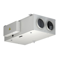
User interface
User interface
The interface, consisting of the remote
keyboard, makes it possible to carry out
all operations related to the use of the
instrument, in particular:
• setting the operation mode
• manage the alarm situations
• check the status of resources
Displays
The device can communicate any type
of information regarding its status, con-
no. 3 shielded electrical cables
not shielded (max. length 100 m;
minimum section 0.5 mm
2
)
Layout control unit rear view on the machine
Modelli 55xx
x 5 uscite digitali tensione pericolosa 2A 230Vac ʅ [DO1, DO2, DO3, DO4, DO6]
x 5 uscite analogiche:
o 2 uscite analogiche [AO1, AO2] Open Collector PPM/PWM
o 3 uscite analogiche tensione non pericolosa (SELV (§))
x 2 uscite [AO3-4] 0-10V
x 1 uscita [AO5] 4…20mA/0…20mA
x 6 ingressi digitali
contatto pulito (°) [DI1…DI6]
x 5 ingressi analogici
o 3 NTC* / Digital Input*** [AI1, AI2, AI5]
o 2 NTC* / tensione, corrente** / Digital Input*** [AI3, AI4]
x 1 uscita Open Collector PWM tensione non pericolosa (SELV (§)) [DO5]
*tipo SEMITEC 103AT (10K� / 25°C)
**ingresso in corrente 0…20mA/4…20mA oppure in tensione 0…5V / 0…10V / 0…1V
oppure Ingresso digitale contatto pulito
***ingresso digitale contatto pulito
(°) corrente di chiusura riferita a massa 0.5mA
(§) SELV: (SAFETY EXTRA LOW VOLTAGE)
x SUPPLY Alimentazione 12-24Va / 24Vc
x 5 c Alimentazione Ausiliaria 5Vdc 20mA max
x 12 c Alimentazione Ausiliaria 12Vdc
x N Neutro
x LAN
collegamento a Terminale (KEYBoard) / SE6xx (max 100m)
x TTL Seriale TTL per collegamento a Multi Function Key
x /C RTC
x RS-485 /S Seriale RS-485 a bordo
per collegamento a sistemi di supervisione
/M Modbus Mas
ter
SMP55xx/C
SMP55xx/C/S
Supply
Supply
GND GND
AI5
DI1DI2
DI3DI4DI5
DI6AO2
AI4
AI2
AI3
AI1
AO
DO3
DO3
RS-485
G3
/S Models
only
54 +
-
G
RS-48
SMD55xx/C/S(/M)
SMD55xx/C - SMD55xx/C/S
SMC55xx/C - SMC55xx/C/S
SE655
Supply
Supply
GNDGND
AI5
DI1 DI2
DI3 DI4 DI5
DI6
AO2
AI4
AI2
AI3
AI1
87
6
5
1211
10
9
6
RS-485
/S Models
only
+
-
G
RS-48
AO
G3 54
RED
BLUE
BLACK
figuration and the alarms through the
display and LEDs on the front side.