20
System types
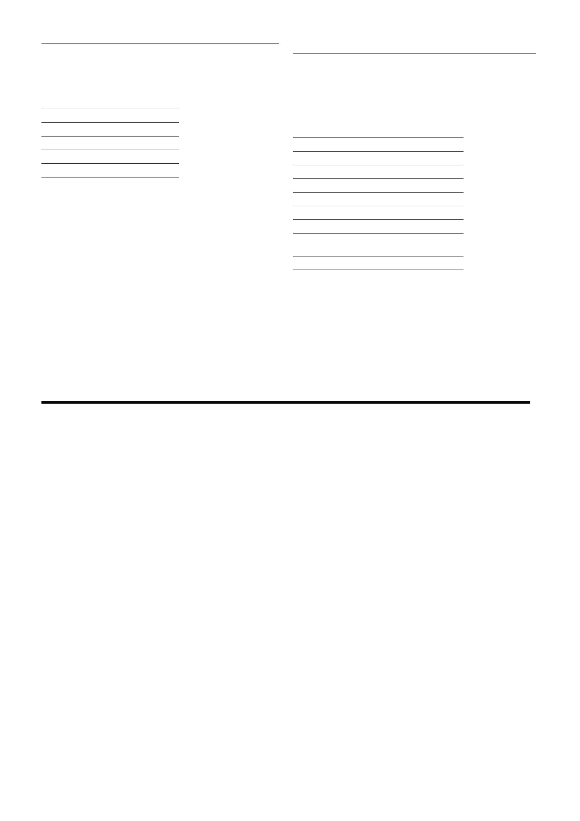
The fan coil units are designed for 2 and 4
pipe systems with constant or variable
flow, with variants of:
- 2 pipe system with 3 and 4 row coils
- 4 pipe system with 3 row coil and 1 row
heating only accessory coil.
Airflow
The airflow is controlled by a control panel
(accessory).
The multi-speed fan-motor allows the
control panel to connect to the 3 speeds
that produce the ideal system available
static pressure.
THERMAL HEAT EXCHANGER COIL
Main coil 3 and 4 rows.
Heating only coil of 1 row, only with
versions with 3 row coil (accessory).
The main coil, reversible during
installation, is designed to ensure an
high heat transfer, ideal for applications
in sensible environment.
FILTER SECTION
Air intake filter, easily extracted for
periodic cleaning. Manufactured from
renewable materials and can be vacuum
cleaned.
Filtration class G3. Flame retardant to M1
NF F 16-101.
FAN ASSEMBLY
Double inlet centrifugal fans designed for
low noise levels.
The fans are directly linked to the electric
motor shaft.
The electric motor is isolated by elastic
supports.
The VES fan coil units are provided with
multi-speed motors. The 3 operating
speeds can be selected by modifying the
connections in the motor electric box.
The fan coil units are supplied with the
connections to the standard velocities.
Refer to the wiring diagram before
modifying the motor connections.
VES0_ - VES1_ - VES2:
6 speed fan-motor.
VES3:
7 speed fan-motor.
STRUCTURE
Manufactured in galvanised sheet steel
of adequate thickness. Class 1 internal
insulation.
Posterior part has fixing holes for
installation.
Intake and discharge openings are
designed to connect the fan coil unit to
any type of air ducting.
The discharge opening includes a
connection flange.
CONDENSATE DISCHARGE
Each unit is supplied with a condensate
drain pan for either vertical or horizontal
installation. The fan coil drain pan has
two condensate discharges (left and
right sides). It is recommended to use
the condensate discharge connection on
the side of the hydraulic connections.
HYDRAULIC CONNECTIONS
The female hydraulic connections are
located on the left side. The coil can be
rotated on site to move the connections
to the right side.
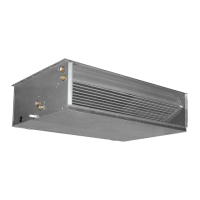
CONTROL PANEL
Various control panels are available to suit
the installation.
Combining the control panels, the
thermostats and the other VMF system
accessories, fully exploits the potential of
the VES units.
The VMF system thermostats allow:
- Control of a single unit and the
accessories.
- Control of a network of 6 units, of 1
master with thermostat and control
panel plus 5 slave units equipped with
thermostats, operating independently as
a function of ambient conditions.
- Control of the VES unit in a complex
network of up to 64 zones with 6 fan
coil units (up to 384 fan coil units with a
single VMF-E5 control board).
COMPONENT DESCRIPTION
OPERATING ENVIRONMENT
dŚĞ ƵŶŝƚƐ ĂƌĞ ĚĞƐŝŐŶĞĚ ĨŽƌ ŝŶƐƚĂůůĂƟŽŶ ŝŶ ĐůŽƐĞĚ ĞŶǀŝƌŽŶŵĞŶƚƐ ŝŶ ĐŽŶĚŝƟŽŶƐ ŽĨ
ƵƌďĂŶŶŽŶͲŵĂƌŝŶĞĂƚŵŽƐƉŚĞƌĞǁŝƚŚŶŽŶͲĐŽƌƌŽƐŝǀĞĂŶĚŶŽŶͲĚƵƐƚLJĐŚĂƌĂĐƚĞƌŝƐƟĐƐ
hŶĚĞƌ ŶŽ ĐŝƌĐƵŵƐƚĂŶĐĞƐ ƚŚĞ ĨŽůůŽǁŝŶŐ ĐŽŶĐĞŶƚƌĂƟŽŶƐ ŽĨ ƉŽůůƵƚĂŶƚƐ ŝŶ ƚŚĞ Ăŝƌ ŝŶ
ǁŚŝĐŚƚŚĞƵŶŝƚŵƵƐƚŽƉĞƌĂƚĞƐŚĂůůďĞĞdžĐĞĞĚĞĚ
SO
2
фϬϬϮƉƉŵ
H
2
S фϬϬϮƉƉŵ
NO,NO
2
фϭƉƉŵ
NH
3
фϲƉƉŵ
N
2
O фϬϮϱƉƉŵ
dŚĞ ƵŶŝƚ ƐŚŽƵůĚ ŶŽƚ ďĞ ŝŶƐƚĂůůĞĚ ŝŶ ůŽĐĂƟŽŶƐ ĐŚĂƌĂĐƚĞƌŝnjĞĚ ďLJ ƚŚĞƉƌĞƐĞŶĐĞŽĨ
ŇĂŵŵĂďůĞŐĂƐĞƐŽƌĂĐŝĚŝĐŽƌĂůŬĂůŝŶĞƐƵďƐƚĂŶĐĞƐ
KƚŚĞƌǁŝƐĞ ƚŚĞ ĐŽŝůƐ ĂŶĚ ƚŚĞ ŝŶƚĞƌŶĂů ĐŽŵƉŽŶĞŶƚƐ ŽĨ ƚŚĞ ĞƋƵŝƉŵĞŶƚ ĐŽƵůĚ ƐƵīĞƌ
ƐĞƌŝŽƵƐĂŶĚŝƌƌĞƉĂƌĂďůĞĚĂŵĂŐĞĨƌŽŵĐŽƌƌŽƐŝŽŶ
WARNINGS FOR THE QUALITY OF THE WATER CIRCULATING
IN THE COILS
/ƚŝƐƌĞĐŽŵŵĞŶĚĞĚƚŽƉĞƌĨŽƌŵĂŶĂŶĂůLJƐŝƐŽĨƚŚĞǁĂƚĞƌĐŝƌĐƵůĂƟŶŐŝŶƚŚĞĐŽŝůĨŽĐƵƐŝŶŐ
ŽŶƚŚĞƌĞƐĞĂƌĐŚŽĨƚŚĞƉŽƐƐŝďůĞƉƌĞƐĞŶĐĞŽĨďĂĐƚĞƌŝĂ;ĚĞƚĞĐƟŽŶŽĨŝƌŽŶďĂĐƚĞƌŝĂĂŶĚ
ŵŝĐƌŽͲŽƌŐĂŶŝƐŵƐ ƚŚĂƚĐĂŶ ƉƌŽĚƵĐĞ ,Ϯ^Žƌ ĐŚĞŵŝĐĂůůLJƌĞĚƵĐĞ ƐƵůƉŚĂƚĞƐͿĂŶĚ ŽŶƚŚĞ
ĐŚĞŵŝĐĂůĐŽŵƉŽƐŝƟŽŶŽĨƚŚĞǁĂƚĞƌƚŽƉƌĞǀĞŶƚĐŽƌƌŽƐŝŽŶĂŶĚĨŽƵůŝŶŐŝŶƐŝĚĞƚŚĞƚƵďĞƐ
dŚĞǁĂƚĞƌĐŝƌĐƵŝƚŵƵƐƚďĞƐƵƉƉůŝĞĚĂŶĚƌĞƉůĞŶŝƐŚĞĚǁŝƚŚƚƌĞĂƚĞĚǁĂƚĞƌƚŚĂƚĚŽĞƐŶŽƚ
ĞdžĐĞĞĚƚŚĞƚŚƌĞƐŚŽůĚůĞǀĞůƐŝŶĚŝĐĂƚĞĚďĞůŽǁ
dŽƚĂůŚĂƌĚŶĞƐƐŝŶŵŵŽůů ůфŵŵŽůůůфϭϱ
Chlorides [CL
-
] фϭϬŵŐůŝƚƌĞ
^ƵůƉŚĂƚĞƐ^K
4
2-
] фϯϬŵŐůŝƚƌĞ
Nitrates [NO
3
-
] сϬŵŐůŝƚƌĞ
ŝƐƐŽůǀĞĚŝƌŽŶ фϬϱŵŐůŝƚƌĞ
ŝƐƐŽůǀĞĚŽdžLJŐĞŶ 4 < [O
2
фϵŵŐůŝƚƌĞ
ĂƌďŽŶĚŝŽdžŝĚĞK
2
] фϯϬŵŐůŝƚƌĞ
ZĞƐŝƐƟǀŝƚLJ ϮϬKŚŵͼŵфZĞƐŝƐƟǀŝƚLJф
ϱϬKŚŵͼŵ
Ɖ, ϲϵфƉ,фϴ