8
IVES0LJ 1707 - 5880761_01
SELECTION CRITERIA
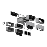
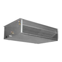
The VES wall-ceiling mounted fan coils are
suitable for both vertical and horizontal
ducted installations.
VES is designed to operate at the 3
default speeds described in the manual.
In case of ducted installations, where
the duct pressure drops are significant,
the VES version allows obtaining the
necessary static pressure to ensure
proper air flow rate by modifying the
settings of the connections on the
electrical box on the motor. VES enables
you to select 3 speeds among the 6/7
speeds available on the motor.
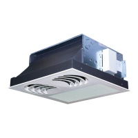
All versions must be combined with a
control panel (accessory), refer to the
features and the compatibility of the
control panels supplied as accessory.
Several accessories are available for VES
series fan coils, sometimes they cannot
be overlapped. The compatibility of the
accessories with the selected fan coil
must be checked. The manual gives the
description, a diagram and compatibility
of each accessory.
The information regarding installation is
inserted in the manuals accompanying
each fan coil and each accessory. This
manual gives general information for
good installation. It also gives diagrams
with dimensions of the fan coils and
wiring diagrams with connection to
control panels.
The main technical data for the VES fan
coils is summarised in the tables.
The sensitive and total cooling yields at
maximum speed depending on the
temperature of the water entering, of
its heat drop and temperature of the air
with dry bulb and wet bulb respectively
for sensitive capacity and total cooling
capacity are stated in the table and are
referred to the maximum speed. The
performance at medium and minimum
speed are obtained by multiplying the
values in the table by the corrective
factors indicated.
The pressure drops on the water side,
respectively for 3/4-row coils (heating
and cooling) and 1-row coils (heating
only) are shown in the charts.
The correction factors in functioning with
glycol water in cooling and heating
modes are stated in the graphics per
percentages of glycol of 10%, 20% and
35%.
The heating capacity produced by
the 3/4-row coils and 1-row coils,
depending on the water flow rate and
the temperature difference between
the incoming water and incoming air,
is specified graphically and refers to
the maximum speed. The performance
at medium and minimum speeds are
obtained by multiplying the values from
the charts at maximum speed by the
corrective factors indicated.
The sound pressure and power level of
the fan coils at the various speeds is
stated in separate tables.
For the ducted installations the sound
power level is expressed in terms of
air flow rate and static pressure and is
represented by graphics in our selection
programs.
The static pressure of the wall/ceiling
mounted versions based on the air flow
rate and fan speed, are shown in table
form, the curves are indicated for each
of the speeds of reference.
For the sizing of the ducted suspended
version it is recommended to proceed
as follows: choose a size which, in
rated flow conditions, has a capacity
immediately higher than that required;
draw the pressure drops curve of the
duct on the flow rate-static pressure
diagram related to the current unit, thus
locating the operation points of the unit
at different speeds. Based on the flow
rate values corresponding to the above-
mentioned points, obtain the correction
factors that allow you to calculate the
capacity in the actual air flow rate
conditions.
The above procedure allows choosing
whethe r to m odify th e motor
connections settings.
The units are designed for installation in closed environments
in 'urban’, non-marine atmosphere conditions that are not
corrosive or dusty.
The following concentrations of the air polluting factors where
the unit must operate must not be exceeded under any
circumstances:
SO
2
< 0.02 ppm
H
2
S < 0.02 ppm
NO,NO
2
< 1 ppm
NH
3
< 6 ppm
N
2
O < 0.25 ppm
The unit must not be installed in areas characterised by the
presence of flammable gases or acidic or alkaline substances.
Otherwise the coils and the internal components of the
equipment might undergo serious and permanent damage in
terms of corrosion.
Warnings for the quality of water circulating in the coils. We
recommend performing an analysis of the water circulating
in the coil focused on searching for any bacteria (detection of
iron bacteria and micro-organisms that can produce H2S or
chemically reduce sulphates) and the chemical composition of
the water itself to prevent corrosion and encrustations inside
the pipes.
The water circuit must have all the components, such as for
instance relief and drainage systems, shut-off valves and that
the results of the analysis performed suggest are necessary to
ensure suitable water treatment. The water treatment system
must ensure compliance with the following chemical and
physical parameters:
Total hardness in mmol/l l < mmoll/l < 1.5
Chlorides [CL
-
] < 10 mg/litre
Sulphates [SO
4
2-
] < 30 mg/litre
Nitrates [NO
3
-
] = 0 mg/litre
Dissolved iron < 0.5 mg/litre
Dissolved oxygen 4 < [O
2
] < 9 mg/litre
Carbon dioxide [CO
2
] < 30 mg/litre
Resistivity 20 Ohm∙m < Resistivity < 50 Ohm∙m
pH 6.9 < pH < 8
OPERATING ENVIRONMENT