Do you have a question about the AERMEC WMT20 and is the answer not in the manual?
Explanation of symbols and terms used in the wiring diagram.
Definitions for terms related to output control and operational parameters.
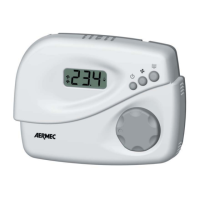
Controls the power state of the controller, turning it on or off.
Allows cycling through fixed fan speeds (F11, F12, F13) and automatic mode.
Navigates display readouts for set-point, supply pipe temperature, and economy function.
Adjusts the desired room temperature (set-point) directly.
Describes the 3-digit LCD display for temperatures and settings.
Explains the use of a supply water sensor for mode selection and cut-off function.
Details room and supply water temperature acquisition using NTC sensors.
Inhibits fan operation when supply water is not hot enough in heating mode.
Enables an energy-saving mode by adjusting the set-point temperature.
Detailed explanation of all installer configuration parameters (P01-P35).
| Brand | AERMEC |
|---|---|
| Model | WMT20 |
| Category | Network Router |
| Language | English |