24
The faster the fan speed the more fan symbols are turned on will be turned
on as faster the fan speed gets. Besides the ‘fan’ symbols, the display can
show two further symbols, which identify that the relevant valve is open.
Symbols can also be flashing, to explain that the relevant output should be
turned on, yet it is temporarily disabled by another function.
As an example, outputs are disabled in the following situations:
- The cut-off thermostat is inhibiting the fan;
- The window contact is inhibiting the regulation.
HEATING/COOLING SELECTION
Cooling (summer) or heating (winter) modes are selected by keeping the
‘ ‘, button depressed for some seconds, until the display shows one of the
following words (meaning the current mode):
Hea Heating mode (winter)
COO Cooling mode (summer)
Then, by pressing the ‘speed’ button, the user can actually choose the
desired mode, cycling between heating and cooling. Depressing any of
the other buttons results in quitting the menu and in the storage of the
preferred configuration data.
settings. All temperatures shown must be intended in Celsius degrees
(centigrade).
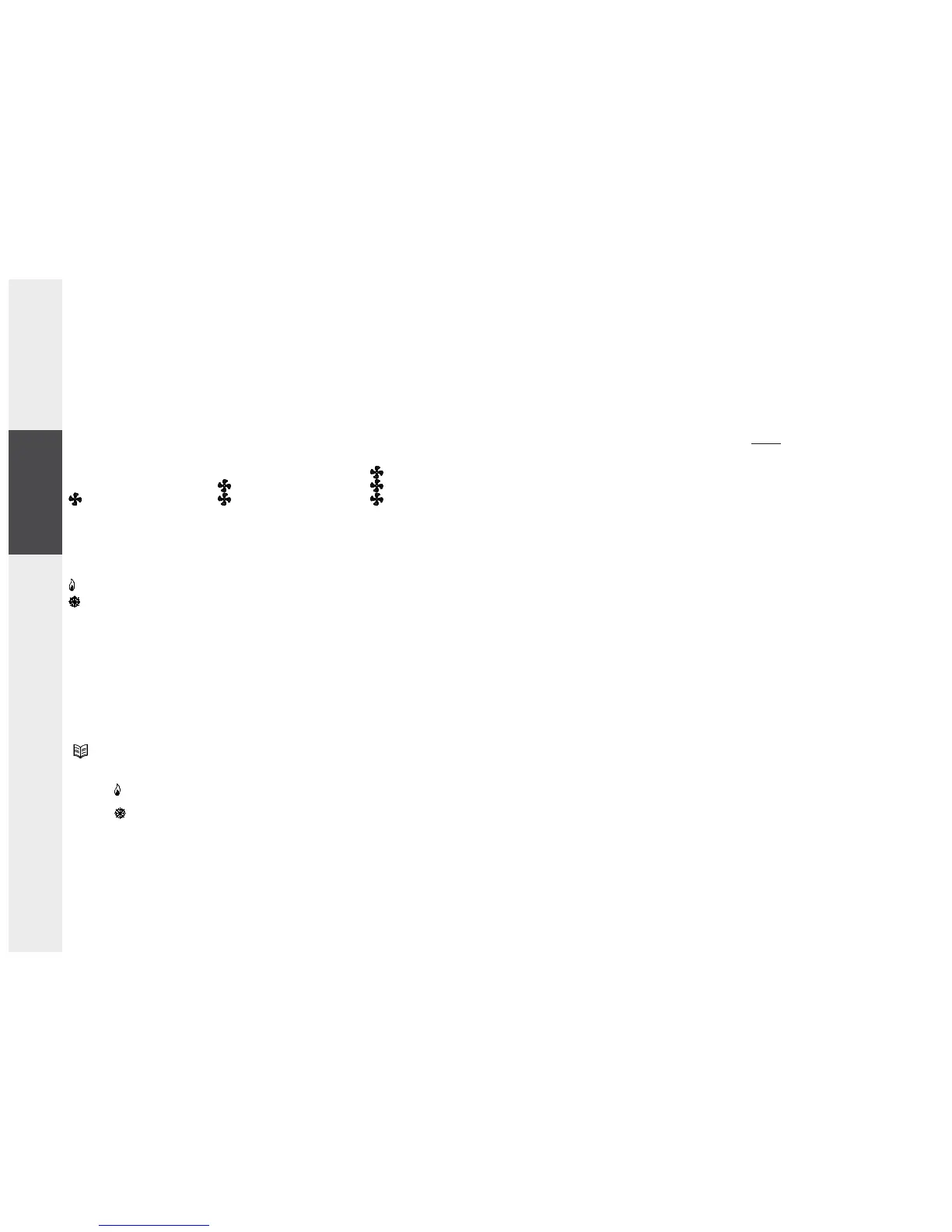
On the display there are also some symbols which report about the current
state of the outputs: fan and valves.
The fan symbols are related to the fan motor state: when all fan symbols
are turned off then the fan is actually off, meanwhile when some of them
are turned on the state of the fan respects the following table:
In case the controller is configured for remote or automatic heating/cooling
selection it is not allowed to enter in the heating/cooling selection menu.
INSTALLATION
To install the controller follow these directions:
1. Remove the plastic cover pressing (with the help of a tool like a
screwdriver) the plastic tooth located in the lower slot as indicated in
Fig. 1 raising, at the same time, the front cover as indicated in Fig. 2.
2. Unmount the plate fixed at the controller back by pressing the plastic
tooth shown in A, Fig. 3 and, at the same time, pull the plate to the
bottom until it becomes free from the plastic base.
3. Fix the plate to the wall through the two holes using the correct
distance between holes (60 mm or 83 mm).
4. Mount the controller base on the wall plate by fitting the base teeth
in the relevant holes on the wall plate, then apply a slight pressure
towards the bottom until the plate fixing tooth snaps (Fig. 4).
5. Make electrical wirings passing the cables through the rectangular
opening and according to the ‘ Wiring ‘ section.
6. Use, as shown in B, Fig.4, the 2 screws supplied in order to securely fix
the thermostat to the relevant back plate.
7. Close the controller coupling the two plastic teeth located in the upper
back part of the plastic cover with the relevant holes of the base. Then,
after ensuring that the knob is correctly coupling to its hole, apply a
slight pressure on the front cover towards the wall until the closing
plastic tooth snaps.
WIRINGS
This controller can be powered either with 230V~ or with 24V~.
The controller is factory configured by default for a 230V~ operation with
the relevant jumper in position JP1. For the 24V~ operation it is necessary
to move the jumper from position JP1 (Fig. 3) to position JP2 (Fig. 3). As
shown in Fig. 5 and 6 terminals 5 and 6 are provided for power supply. Use
the same supply voltage which powers the thermostat (terminals 5 and
6) to power the valves. In case the thermostat is powered with a safety
speed 3 (HI) speed 2 (ME)
speed 1 (LO)
heating valve open
cooling valve open
ENGLISHESPAÑOL DEUTSCH ITALIANOFRANÇAIS