ACCEPTANCE TESTING
7-19
External FM frequency response (ALC off, DC coupled)
Test procedure
UUT
2305
Modulation meter
C2368
RF
OUTPUT
EXT MOD
INPUT
OUTPUT
Temporary
connection
RF INPUT LF
OUTPUT
INPUT
Function generator
DVM
50 loadΩ
Audio analyzer
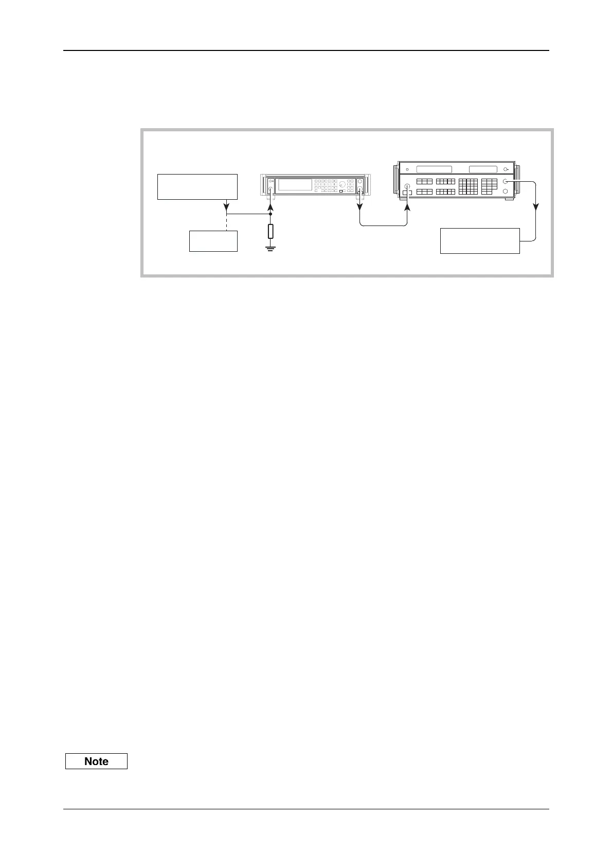
Fig. 7-9 External modulation and modulation distortion test set-up
30 Hz to 275 kHz
(1) Connect the test equipment as shown in Fig. 7-9.
(2) On the UUT set:
[CARR FREQ] 15 [MHz]
[RF LEVEL] 0 [dB]
[MOD] 50 [kHz]
[SOURCE ON/OFF] (to enable modulation source)
[MOD ON/OFF] (to enable modulation)
[MENU] 20 [ENTER]
The UUT enters the Modulation Mode menu
Select FM ext using [NEXT]
[MENU] 30 [ENTER]
The UUT enters the Modulation Source menu.
Select Ext using [NEXT]
Select 2 to select DC coupling
(3) Set the function generator to give 1 V RMS (1 V peak for units with Option 10), 1 kHz sine
wave.
(4) On the modulation meter, select CAL, FM, 10 Hz
⇒ 300 kHz filter.
(5) On the modulation meter, check that the FM reading is between 47.5 kHz and 52.5 kHz, then
set a reference using the relative function.
(6) Set the function generator to each of the frequencies shown in Table 7-25, checking that the
rel
ative readings on the modulation meter are within specification.
(7) At those frequencies indicated in Table 7-25, set the modulation meter LF output control to
m
id position and measure the AF distortion on the audio analyzer, checking that the results
are within specification.
0 Hz (DC)
To measure the FM deviation at DC, it is necessary to use the DC offset facility on the function
generator proceeding as follows:



 To Next Page