FIRST-TIME USE
4-10
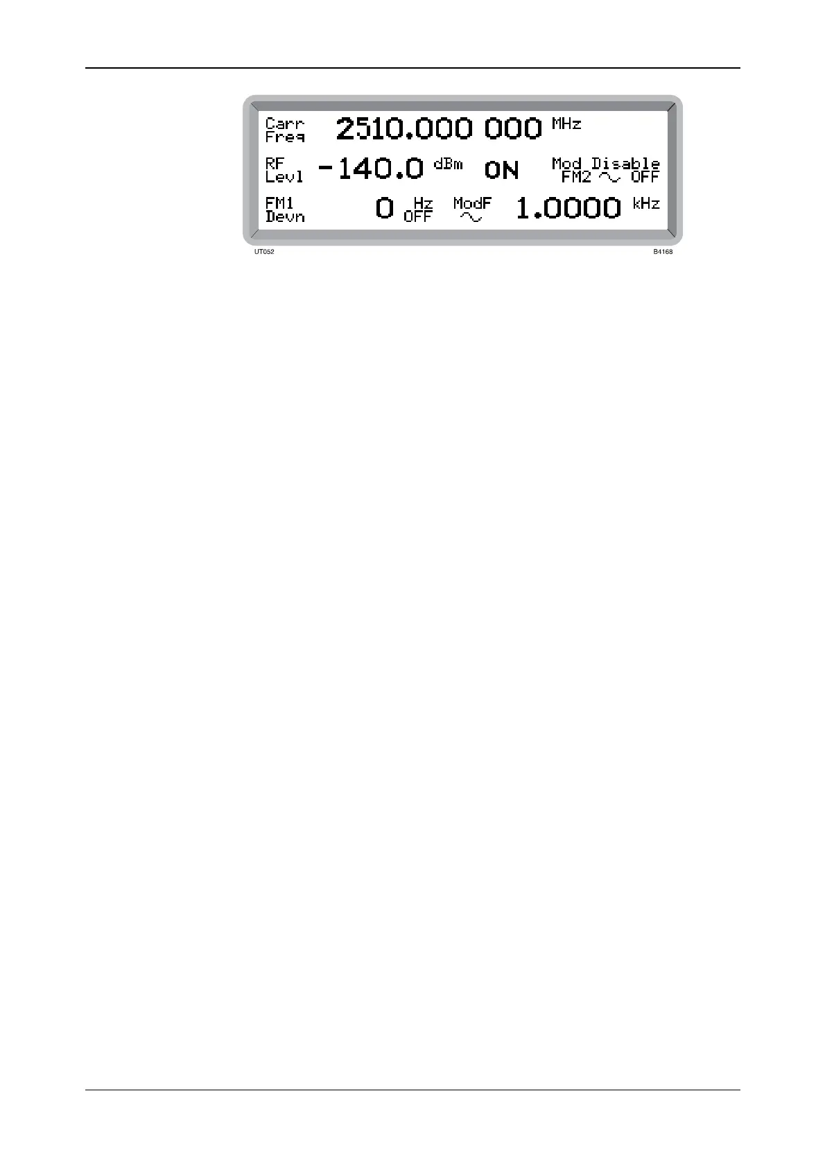
Fig. 4-6 2025 main screen in normal operation showing default display
Display
Before entering any parameters it is useful to look at the effect that pressing various keys has on
the display. The display is divided into a number of fields as shown in Fig. 4-7.
Carrier frequency field
When you press [CARR FREQ] it causes Carr Freq to be highlighted and your data entry is
recognized as a frequency setting. Ext is displayed when the instrument is locked to an external
standard.
Memory field
When you press the [STO] or [RCL] key it causes STO or RCL to be highlighted respectively.
Your data entry is recognized as a memory location number. The type of recall − FREQ, FULL or
RAM (or sequence number for memory sequencing) − is also shown.
Error message field
Error messages are displayed when, for example, you exceed a parameter limit. A list of error
messages is given at the end of this chapter.
RF level field
When you press [RF LEVEL] it causes RF Level to be highlighted and your data entry is
recognized as a level setting. Units and unit type are displayed together with the carrier ON or
OFF state. When selected, Atten Lock is displayed unless overwritten by Offs when an RF level
offset has been enabled. This field is also used to display the SINAD measurement and weighting
filter used.
Modulation field
When you press [MOD] it causes the currently selected type of modulation to be highlighted and
your data entry is recognized as a modulation depth or deviation setting. Modulation ON or OFF
is also shown.
Modulation source field
When you press [MOD SOURCE] it causes the currently selected internal modulation source or
external coupling to be highlighted. For an internal source a sine, triangle or square wave symbol
is shown. Your data entry is recognized as a modulating frequency. For an external source AC,
DC or ALC coupling is shown.
When the instrument is operating under remote control REM is displayed.



 To Next Page