7-33
TEST PROCEDURES FOR INSTRUMENTS FITTED
WITH OPTION 3
RF output
Specification
Level range:
−140 dBm to +25 dBm, uncalibrated above +19 dBm for carrier
frequencies from 1.2 GHz to 2.4 GHz and uncalibrated above +14 dBm
for carrier frequencies above 2.4 GHz.
Accuracy:
As per the standard instrument for output levels below +7 dBm.
For output levels above +7 dBm and over a temperature range of 17
°C
to 27
°C:
±1 dBm 9 kHz to 1.2 GHz <23 dBm
±1.5 dBm 9 kHz to 1.2 GHz <25 dBm
±2 dBm 1.2 GHz to 2.51 GHz
Temperature coefficient
<
±0.02 dB/°C to 1.2 GHz ,
<
±0.03 dB/°C to 2.51 GHz
Test equipment
Description Minimum specification Example
Power meter
±0.1 dB from 9 kHz to 2.51 GHz
Aeroflex 6960B
and 6932
Measuring
receiver
0 dBm to −127 dBm; 2.5 MHz to 2.51 GHz
Agilent 8902A
with 11722A
sensor and
11793A down
converter
Signal generator +8 dBm from 32.5 MHz to 2.54 GHz Aeroflex 2041
RF level frequency response
Test procedure
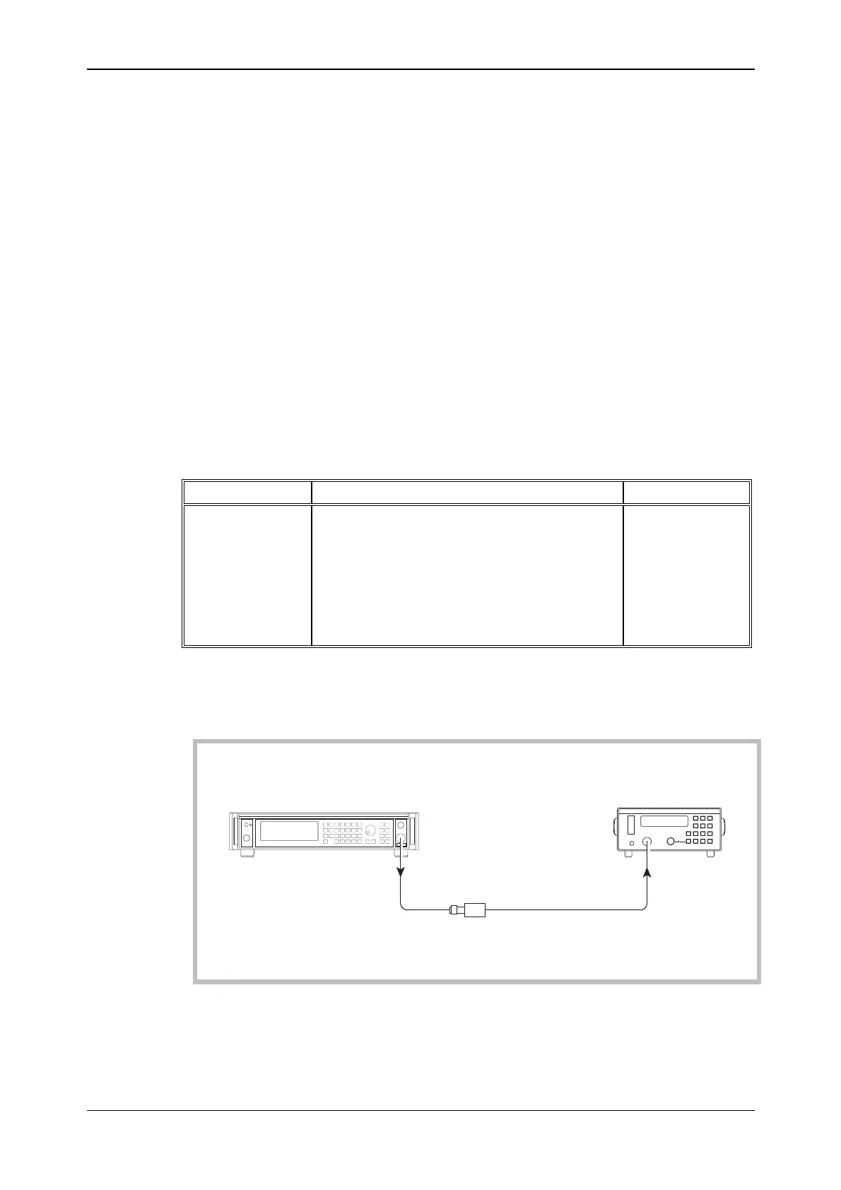
UUT
C2373
6932
RF OUTPUT
SENSOR
INPUT
Power
sensor
6960B
RF power meter
Fig. 7-17 RF output test set-up
(1) Perform AUTO ZERO and AUTO CAL on the power meter.