2-94 Subject to Export Control, see Cover Page for details.
2-5-2. TYPICAL VEHICLE INSTALLATION TEST (cont)
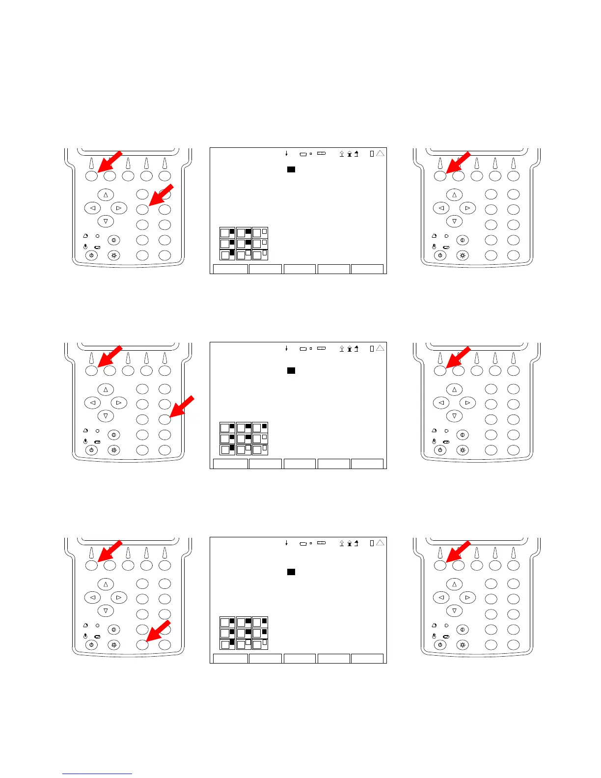
8. With the cursor on the Modulation Meter Field, press the F1 “Edit” Key and the 3 Key to
display the Modulation Meter in the top right portion of the Duplex Test Screen. Press the
F1 “Done” Key to save the setting.
2
4
6
8
0
1
9
7
5
3
DUP LEX TE ST SETUP
Modul ation Meter 3 DCS Decode 0
R SSI M eter : 0 Audio Leve l 0
R F Er ro r Met er: 0
R F Power Me ter 0
SINAD Meter 0
D istortion M eter: 0
AF Counte r 0
DTMF Decode 0
Do n e Return
1
4
3
6
9
4 1 20 29
2
4
6
8
0
1
9
7
5
3
9. With the cursor on the RSSI Meter Field, press the F1 “Edit” Key and the 6 Key to display
the RSSI Meter in the middle right portion of the Duplex Test Screen. Press the F1 “Done”
Key to save the setting.
2
4
6
8
0
1
9
7
5
3
DUP LEX TE ST SETUP
Modul ation Meter 3 DCS Decode 0
R SSI Meter : 6 Audio Leve l 0
R F Er ro r Met er: 0
R F Power Me ter 0
SINAD Meter 0
D istortion M eter: 0
AF Counte r 0
DTMF Decode 0
Do n e Return
1
4
3
6
9
4 1 20 29
2
4
6
8
0
1
9
7
5
3
10. With the cursor on the RF Error Meter Field, press the F1 “Edit” Key and the 9 Key to display
the RF Error Meter in the bottom right portion of the Duplex Test Screen. Press the F1
“Done” Key to save the setting.
2
4
6
8
0
1
9
7
5
3
DUP LEX TE ST SETUP
Modul ation Meter 3 DCS Decode 0
R SSI M eter : 6 Audio Leve l 0
R F Er ro r Met er: 9
R F Power Me ter 0
SINAD Meter 0
D istortion M eter: 0
AF Counte r 0
DTMF Decode 0
Do n e Return
1
4
3
6
9
4 1 20 29
2
4
6
8
0
1
9
7
5
3
 Loading...


