2-102 Subject to Export Control, see Cover Page for details.
2-5-5. MEASURING DTF (Distance to Fault)
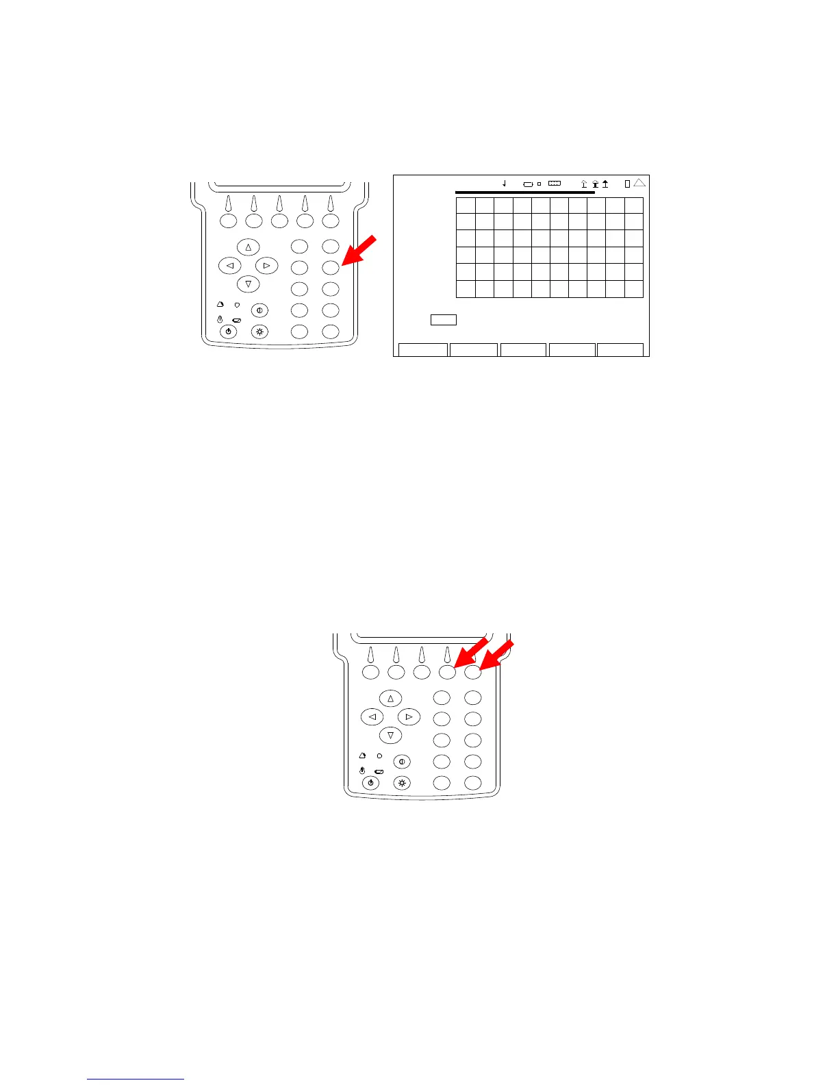
1. With the System Menu displayed, press the 4 Key to display the ANT-Cable Test Screen.
2
4
6
8
0
1
9
7
5
3
ANT-CABLE TEST
7.00
2009-01-06
11:35:30
SWR
1.00
35.0 MHz 45.0
Type: SWR Freq (MHz): 40.0 Span (MHz): 10.0
Sta rt (MHz): 35.0 Sto p (MHz): 45.0
Edit
Return
Ho l d
Cal
Ma rke r
4 1 20 29
2. Press the F4 “Cal” Key to start the SWR Calibration. Follow the instructions on the screen
to complete the SWR Calibration. When SWR Calibration is completed (“Calibration
Complete” displayed on screen), press the F5 “Done” Key to return to the ANT-Cable Test
Screen.
NOTE: Calibration must be performed at the point the operator is connecting to the
system under test:
• If the supplied test cable is being used to connect to the system
under test, calibration is to be performed at the end of the test
cable. Test cable should not to exceed four feet in length.
• If the system under test cable is being connected directly to the
3500 / 3500A, then calibration is to be performed at the SWR
Connector.
2
4
6
8
0
1
9
7
5
3
NOTE: Once the SWR Connection is calibrated, the SWR Connector remains in the
calibration state until the user changes the point of connection to the UUT. The
ANT-Cable Test Screen displays the Date and Time of the last Calibration above
the Graphical Display.
 Loading...


