Subject to Export Control, see Cover Page for details. 2-105
2-5-5. MEASURING DTF (Distance to Fault) (cont)
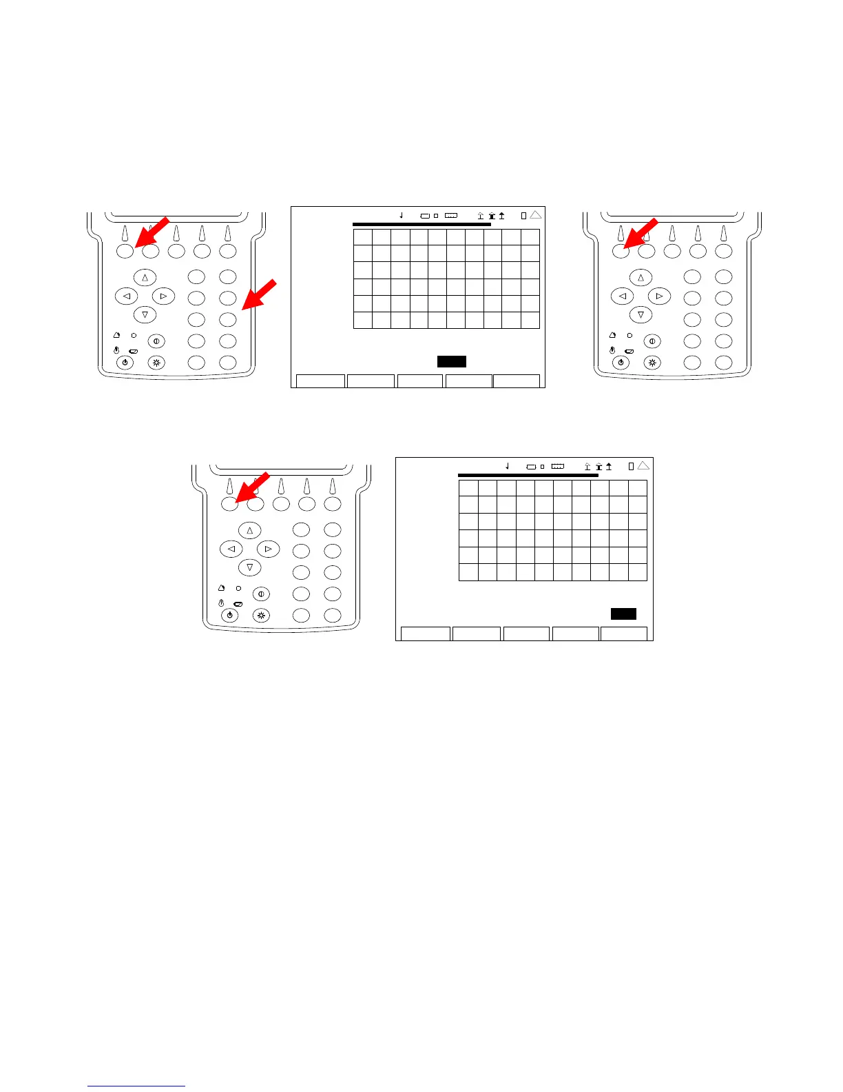
9. With the cursor on the Est Length Field, press the F1 “Edit” Key and use the Number Keys to
select the Estimated Cable Length. (The Estimated Cable Length is the total Cable Length
of the System Under Test plus 15%.) Press the F1 “Done” Key to save the setting.
2
4
6
8
0
1
9
7
5
3
AN
-CABL E TEST
0.00
200 9-01 -06
11 :35 : 30
dB
-50 .0
0.0 ft 408.8
Cable: RG-8x Velocity: 0.66 Loss: 10.00
Est L ength: 40 8.8 Unit Feet
Edit Return
Ho l
Cal
Scal
41 20 29
2
4
6
8
0
1
9
7
5
3
10. With the cursor on the Unit Field, press the F1 “Edit” Key to select Feet or Meters.
2
4
6
8
0
1
9
7
5
3
ANT-CABLE TEST
0.00
2009-01-06
11:35:30
dB
-50 .0
0.0 ft 408.8
Cable: RG-8x Velocity: 0.66 Loss: 10.00
Est L ength: 408.8 Unit Feet
Edit
Return
Ho l d
Cal
Scale
4 1 20 29
11. Connect the System Under Test to the SWR Connector at the point of calibration.
12. The Graphical Display is updated approximately every 20 seconds. Allow at least two
updates of the Graphical Display to insure data is valid.
 Loading...


