1-16 Subject to Export Control, see Cover Page for details.
1-4. PRINCIPLES OF OPERATION (cont)
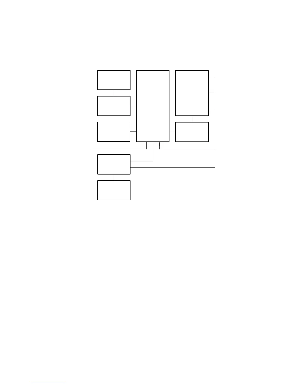
The 3500A contains the following assemblies:
LCD
T/R
AUDIO I/O
RF
DIGITIZER
POWER
SUPPLY
BATTERY
MULTI-
FUNCTION
RF SWR
ANT
REMOTE
DC IN
KEYPAD
AUDIO
DVM
AUDIO IN
AUDIO OUT
The Power Supply PCB Assy is responsible for supplying power to the internal modules
for operation and for charging the internal batteries.
The
RF Digitizer PCB Assy converts the baseband signal to a modulated 10.5 MHz Tx IF
which is upconverted in the RF Assy to provide an RF Generator output. The Receive
signals are down-converted to 13 MHz and demodulated to baseband signals.
The
Multi-Function PCB Assy includes the processors, FPGA and memory to send data
from the RF Digitizer PCB Assy through the Power PC to the ColdFire for display on the
LCD Display. Keyboard inputs are processed to provide instructions to the RF Assy.
The
RF Assy consists of the RF Controller PCB Assy and the RF Converter PCB Assy.
The RF Converter PCB Assy converts the 10.5 MHz TX IF to the 2 MHz to 1 GHz RF and
from the 2 MHz to 1 GHz receiver input to the 13 MHz RX IF. The RF Converter PCB Assy
also contains the VSWR coupler and associated circuitry and the Power Termination. The
RF Controller PCB Assy provides the TCXO, LOs and digital circuitry necessary for
software control and for tuning and level control.
The
Audio I/O PCB Assy provides the DVM/Scope, Audio In and Audio Out signals to the
3500A Front Panel.