2-34 Subject to Export Control, see Cover Page for details.
D. ANT-Cable Test Screen (cont)
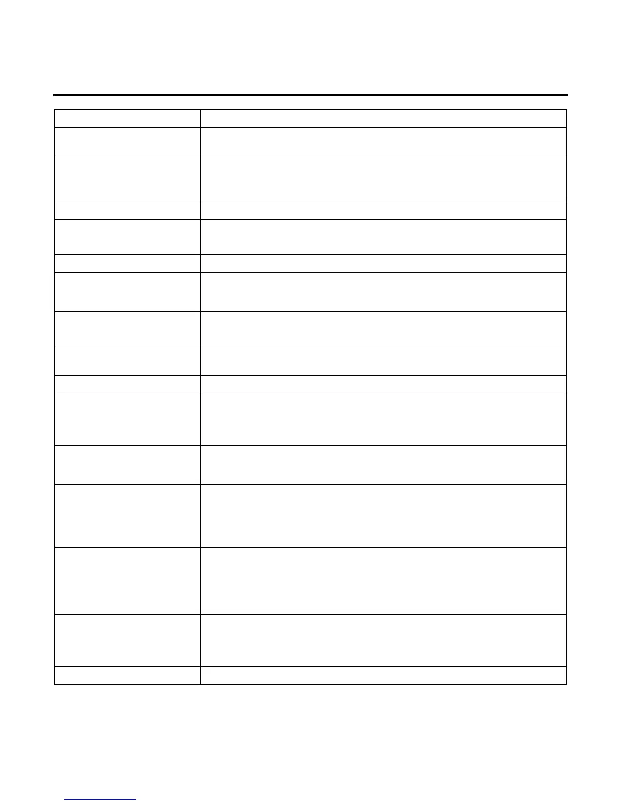
SCREEN FEATURE FUNCTION
VSWR Progress Bar A graphical representation of the percentage completed for the
current measurement.
Marker Used to select and enable one of three markers on the Graphical
Display.
Select: 1 to 3
Marker Status Used to set the Marker selected to ON or OFF.
Delta Used to enable the Delta Marker Function.
Select: 1 to 3
DTF Displays the distance to fault.
Delta (Top) Displays the Delta in SWR/Return Loss between the Active Marker
selected in the Marker Field and the Marker selected in the Delta
Field.
Move/Min/Max Used to move the Active Marker on the Graphical Display.
Select: Max, Min or Move
Left Right Used to move the Active Marker selected in the Marker Field to the
left or to the right on the Graphical Display.
Pos Displays the Horizontal Axis of the Active Marker.
VSWR / dB Displays the reading of the Active Marker.
VSWR Displays the SWR reading.
dB Displays the DTF, RL or LOSS reading.
Delta (Bottom) Displays the Delta in Frequency or Distance between the Active
Marker selected in the Marker Field and the Marker selected in the
Delta Field.
F1 “Edit” / “Done” / “Next” Edit Highlights the selected field to be changed or changes the
field value if the field only contains two selections.
Done Ends the Field Edit and saves the new setting / value.
Next Displays the next pop-up screen.
F2 “Return” / “Save” Return Displays the System Menu (para 2-2-2)
Save Performs a data dump of frames displayed on the screen,
including configurations, readings and settings. The data
dump is stored in a time-stamped ASCII report and can be
retrieved at a later time.
F3 “Hold” / “Resume” /
“Abort”
Hold Freezes the screen.
Resume Restores the screen to active mode.
Abort Stops the action to calibrate the SWR Connector.
F4 “Cal” Instruction pop-ups are displayed to calibrate the SWR Connector.