2-38 Subject to Export Control, see Cover Page for details.
D. ANT-Cable Test Screen (cont)
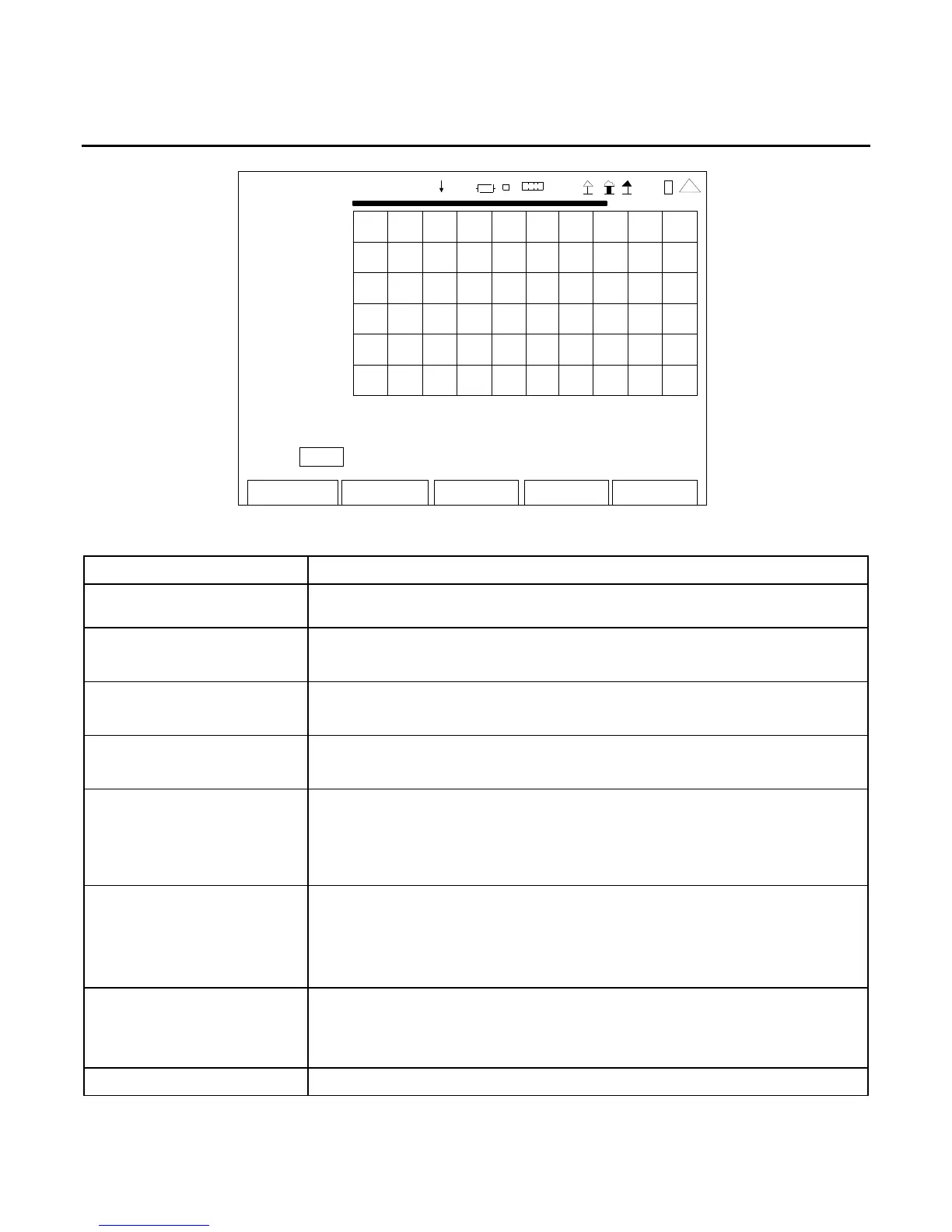
ANT-CABL E TEST
7.0
0.0 0
2009-01 -06
11:35:30
dB
-50.0
0. 1 Ft 415.5
Scale: User Top: 0 Bot tom: -50
Edit Return
Ho l d
Cal
RF
41 20 29
(Scale Mode)
SCREEN FEATURE FUNCTION
VSWR Progress Bar A graphical representation of the percentage completed for the
current measurement.
Scale Used to scale the Vertical Axis of the Graphical Display.
Select: Fixed or User
Top Used to set the upper limit of the Vertical Axis.
Select: -100 to 100
Bottom Used to set the lower limit of the Vertical Axis.
Select: -100 to 100
F1 “Edit” / “Done” / “Next” Edit Highlights the selected field to be changed or changes the
field value if the field only contains two selections.
Done Ends the Field Edit and saves the new setting / value.
Next Displays the next pop-up screen.
F2 “Return” / “Save” Return Displays the System Menu (para 2-2-2)
Save Performs a data dump of frames displayed on the screen,
including configurations, readings and settings. The data
dump is stored in a time-stamped ASCII report and can be
retrieved at a later time.
F3 “Hold” / “Resume” /
“Abort”
Hold Freezes the screen.
Resume Restores the screen to active mode.
Abort Stops the action to calibrate the SWR Connector.
F4 “Cal” Instruction pop-ups are displayed to calibrate the SWR Connector.
 Loading...


