MAI NTENANCE MANUAL
ATC-1400A-2
2-2-2
Page 7
Subj e c t to E x p o rt Co n t r o l, s e e Cover P a ge f o r d etai l s . Feb 2 / 0 9
D. Cal i b r atio n / V eri f i c a tio n P r oce d u r e s
(1) Power S u p p l y
PREREQUISITES: None
TEST E Q U I P M E N T : 1 Digita l M u l t i meter
SET-UP DIA GRAM: None
NOTE: Dur i n g per f o r mance o f t his p r o cedu r e , if a c ert a i n co n d i tio n o r sp e c i fic a t i on
cann o t b e ve r i f ied, r e f er t o a ppro p r i a te a s sembly t e s t pr o c e dur e i n 2-2 - 4 for
test i n g an d r e pai r o f fa u l t y as s e m b l y.
STEP PROCEDURE
1. V erif y o n SW30 1 ( X PDR Deco d e r P C Boar d A sse mb l y ) , di p s witc h # 1 is s e t to
UP and d i p swi t c h #2 i s set t o DOWN (2 - 2 - 2 , Fi g u r e 25).
2. Veri f y o n SW 5 0 1 (DME Rang e P C B oar d A s sembly ) , dip s w i t c h #1 , # 2 an d # 3
are s e t to UP a n d di p s w i tch # 4 is s e t to D O W N ( 2 -2-2 , F i gure 2 5 ) .
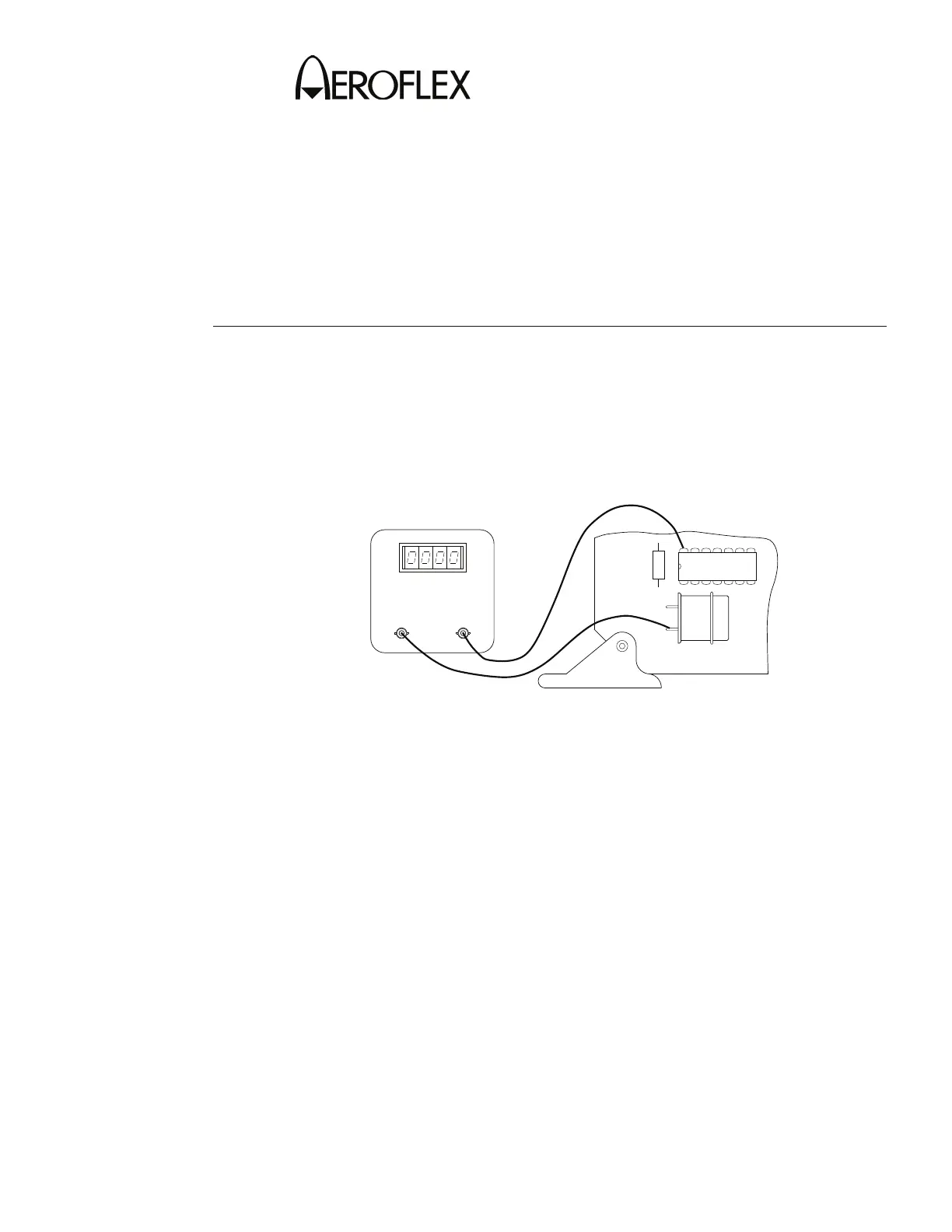
3. Remove Mic r o p r oces s o r PC Bo a r d As s e m b l y (2 - 2 - 2, F i g u r e 2 5 ) p art w a y o ut
from Car d C a ge A s s e mbly a n d conn e c t Dig i t al Mu l t i meter p o s itiv e l ead t o X72 5 ,
pin 1 4 a nd n e g a tive l e ad t o g r oun d ( 2 -2- 2 , F igu r e 2 7).
- +
7506020
VOLTMETER
DIGITAL
X725
Y701
R705
Microp r o c esso r P C Boar d A ssembl y D e t ail
Figu r e 27
4. Reins t a l l Micr o p r o ces s o r PC Bo a r d As s e m b l y i n C a r d Cag e A ssembl y .
5. S et AT C - 1 4 0 0 A-2 P OW E R S w i t c h to O N . V erif y A T C-1400A - 2 f ront p a n el
disp l a ys a r e in a c c orda n c e wit h p ower- u p sel f t e st i n 2 -2- 4 , T able 5 5 .
6. Allo w a 1 0 minu t e w a rm-up p e r i od b e f o re p r o c e edi n g .