CALIBRATION
IFR 4000
Subject to Export Control, see Cover Page for details. Page 4
Jun 1/11
STEP PROCEDURE
8. Enter password (3524) to display the Calibration Screen.
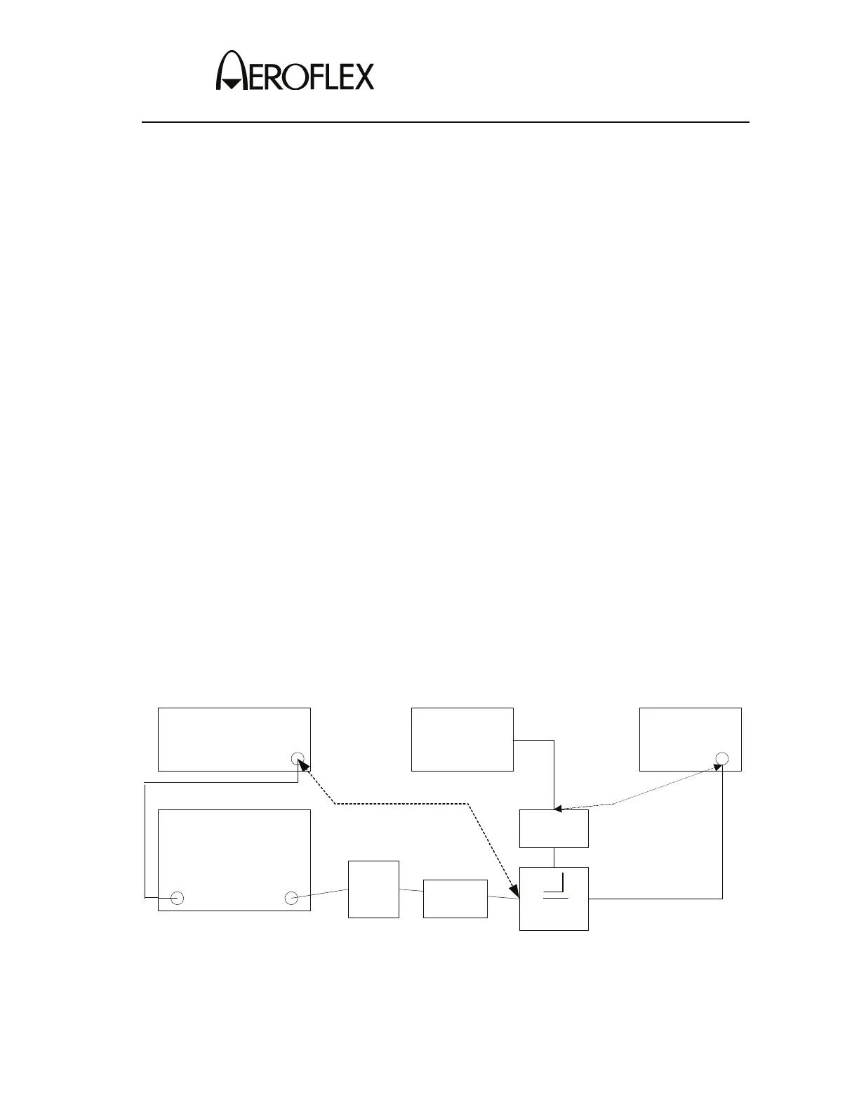
9. Characterize and record the loss of the Power Meter Calibration Setup
(Figure 1):
Measure the loss (at 200 MHz) between the Signal Generator and the 20 dB
attenuator on the coupled port of the directional coupler. Record as A.
Measure the loss (at 200 MHz) between the Signal Generator and the end of
the coaxial cable going to the RF I/O Connector. Record as B.
Subtract Loss (B) from Loss (A) and record.
Characterize Test Setup:
FREQ A B OFFSET
200 MHz
___________ ___________ ___________
10. Characterize and record the loss of the Power Meter Calibration Setup (2-2-3,
Figure 5):
Measure the loss (at 10, 200 and 400 MHz) between the Signal Generator
and the 20 dB attenuator on the coupled port of the directional coupler.
Record as A.
Measure the loss (at 10, 200 and 400 MHz) between the Signal Generator
and the end of the coaxial cable going to the RF I/O Connector. Record as
B.
Subtract Loss (B) from Loss (A) and record.
Characterize Test Setup:
FREQ A B OFFSET
10 MHz
___________ ___________ ___________
200 MHz
___________ ___________ ___________
400 MHz
___________ ___________ ___________
IFR*4000
SIGNAL*GENERATOR
100*W*AMPLIFIER
DIRECTIONAL
COUPLER
POWER*METER
INPUT OUTPUT
RF*OUT
RF *//O
BANDPASS
FILTER
or
LOW-PASS
FILTER
3*dB
ATTENUATOR
20*dB
ATTENUATOR
MEASURE*LOSS
BETWEEN*THESE
POINTS
TEMPORARY*CONNECTION*FOR
SETUP*LOSS*MEASUREMENT
Power Meter Calibration Setup
Figure 1
 Loading...