The Smart-Shift is an advanced electronic vehicle interface technology designed to remotely operate the shifting functions of automatic transmissions in a wide range of vehicles. This system is particularly beneficial for individuals, installing dealers, and driver rehabilitation professionals, offering a solution for various "shifting" needs. The core of the Smart-Shift system consists of a Touchpad, an Actuator with a mounting bracket, a Controller Module, a Vehicle Interface cord, a telco cord, and a Universal installation kit.
Function Description:
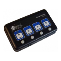
The Smart-Shift system allows for the remote control of an automatic transmission's shifting functions. It is compatible with almost any vehicle equipped with a cable-actuated automatic transmission. The system operates via a small (5.5" x 3.25" x 1") touchpad, which features four illuminated tactile buttons. Each button corresponds to a specific gear and is positioned below an icon representing that gear. An LED indicator next to each icon illuminates when the actuator has successfully reached the programmed position for that gear.
The system incorporates positional feedback, enabling the actuator to precisely position the shifter cable for up to seven selector choices: Park, Reverse, Neutral, Drive, Drive3, Drive2, and Drive1. It's important to note that Drive3, Drive2, and Drive1 may not be available for all vehicles. When the vehicle is in Park and any other gear button is pressed, the actuator moves the shifter cable to the selected gear, stops automatically, and illuminates the corresponding LED indicator. This precise positioning eliminates issues like missed gears or slow actuator movement in traffic.
A key feature of the Smart-Shift is its multifunctional "D" button, which can be programmed for up to four different Drive positions: Drive, Drive3, Drive2, and Drive1. Operation is straightforward: with the vehicle's ignition ON and the brakes applied, pressing any of the four buttons will move the transmission to the selected gear. To activate Drive 3, 2, or 1, the user simply presses the Drive key while already in Drive. Each subsequent press of the Drive key cycles through these low gear positions. The "D" LED will continually flash at different rates to indicate which low Drive gear (3, 2, or 1) is currently selected. To exit any of the low Drives, the user can press any other gear button, and the transmission will switch to that position. The Smart-Shift requires two inputs to operate: the vehicle's ignition must be "On," and the brakes must be applied.
Important Technical Specifications:
- Actuator Stroke: The actuator has a total stroke of 2-1/4 inches. This is a critical specification for ensuring proper interface with the vehicle's transmission shift arm, as the arc of travel from Park to Low gear should be approximately 2-1/4 inches.
- Actuator Positioning Accuracy: The actuator can position itself accurately to within 1/32 inch of travel. This high precision is crucial for reliable and consistent gear selection.
- Power Requirements: The system requires a 12V DC source, connected through a 15 AMP circuit breaker, which is hot only when the vehicle's ignition is ON.
- Brake Light Input: A 12V DC input from the brake light switch wire is essential for the Smart-Shift to operate. The system will not function without this brake light feed.
- Dash Lamp Input: A wire supplying 12V DC to the dash lamp when the dash lights are "On" provides backlight illumination for the touchpad.
- Actuator Cable: The actuator cable is a special shielded, twisted pair cable with three black wires. It is critical NOT to cut the connector end of this cable, as incorrect wiring can lead to damage and void the warranty.
- Touchpad Dimensions: The touchpad is compact, measuring 5.5" x 3.25" x 1".
- Mounting Hardware: The system includes various mounting brackets and hardware, such as #10-32 x 3/8" button head screws, #6-32 x 1/2" spacers, and #6-32 x 3/8" button head screws, along with Blue Loctite® for secure fastening. Specific kits (e.g., KIT-SS-ASSY-08C, KIT-SS-ASSY-04T, KIT-SS-ASSY-05M, KIT-SS-ASSY-19S) are provided for different vehicle models like Chrysler Town & Country/Dodge Grand Caravan, Toyota Sienna, Honda Odyssey, and GM Silverado/Sierra.
Usage Features:
- Intuitive Touchpad Interface: The four illuminated tactile buttons with clear gear icons make gear selection easy and visually confirm the selected gear.
- Multi-Drive Functionality: The "D" button's ability to cycle through multiple Drive positions (Drive, Drive3, Drive2, Drive1) offers flexibility for various driving conditions, with distinct flashing rates for each low gear.
- Safety Interlocks: The system requires the ignition to be ON and the brakes to be applied for operation, preventing accidental shifts.
- Positional Feedback: The LED indicators provide immediate visual confirmation that the actuator has reached the programmed gear position.
- Calibration Mode: The system includes a calibration procedure using actuator control buttons and touchpad buttons to precisely set and store gear positions, ensuring accurate and consistent shifting.
- Lockout Feature Awareness: Users are advised to be aware of OEM transmission lockout features for lower gears, which prevent engagement if the vehicle speed is too high, regardless of the driver's selection.
Maintenance Features:
- Robust Installation Guidelines: The manual provides detailed instructions for mounting the actuator bracket and connecting the shift cable, emphasizing the importance of rigid attachment and proper cable routing to prevent kinks and contact with hot surfaces.
- Cable Protection: Instructions include P-clamping the shift cable periodically and sealing around the harness where it enters the cabin to prevent water and fumes.
- Troubleshooting Assistance: The manual advises contacting EMC Service for assistance if the actuator cannot travel to all four main transmission gears during calibration, or if installation problems are encountered.
- Warranty Information: A warning is provided against cutting and incorrectly wiring the actuator cable, as this will result in damage not covered under warranty.
- Towing Precaution: A critical safety caution states that the EMC Smart-Shift actuator must be either placed in Neutral or the OEM shift cable disconnected from the actuator before attempting to tow the vehicle.
- Blue Loctite® Usage: The consistent recommendation to use Blue Loctite® for securing screws ensures long-term fastener integrity and prevents loosening due to vibration.