water
level
hartford
loops
check
valv
e
hartford
loop
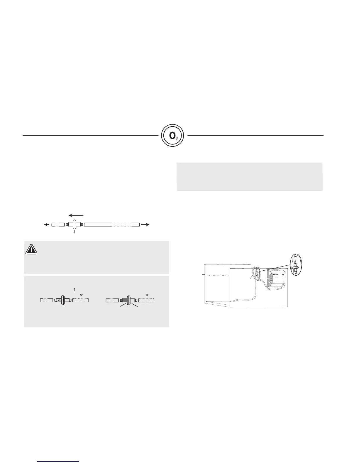
The check valve must allow air to fl ow from in.zone to the
injection point and prevent water from coming back to
in.zone. If needed, blow into the check valve before you
install it to make sure you are installing it the right position.
You may have one of the following check valves:
•Check valve 1: an arrow shows the airfl ow direction;
arrow should point to the spa.
As a second protection against water infi ltration, it is required
perform an Hartford loop installation with in.zone's plastic tube.
Take the 10’ fl exible plastic tube, make two loops as illustrated
and secure it above water level. If it is not possible to place the
loops higher than water level, secure them as high as possible
under the spa skirt. The loop(s) must have a diameter of at least
Connect the longest side of the tube to the injection point, just
tube on the ozone outlet of in.zone
Each in.zone comes with a 10’ 1⁄4” ID fl exible plastic tube and a
Cut the tube at about 1’ from the injection point.
Connect the two sections of the tube on each side of the check
valve (you can add a tie rap on each side of the check valve to
solidify the connection).
• Check valve 2: grey side of the check valve should
face the spa side since the air fl ow is
coming from the clear (transparent) side
of the check valve towards the grey side.
Connect the shortest part of the tube on
the check valve at the other end
. (Refer to injection section,
check valve
to
injection
point
to
in.zone
air flow
±1' ±9'