(12) Press
(13) Press
(14) Press
9 1 to check up time ratio, the ratio value should be in the range of 100±3%
0 8 to check up the working status, “R” means work well
0 1 to check up the measuring data.
Piping Configuration
and
Transducer Position
Note: 1. For heat measurement, please connect PT100 which installed in water supply and water back
pipe to T1, TX1, T2, TX2, GND terminal.
2. After setting parameter, remember to store parameter in MENU 26, to avoid parameter lose
after turn off.
2.5
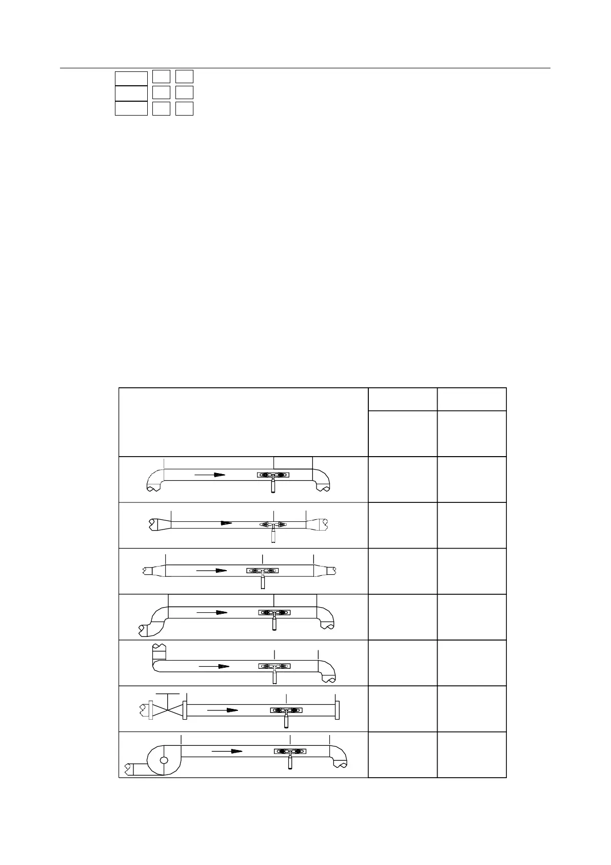
Transducers Mounting Allocation
The first step in the installation process is the selection of an optimum location in order to obtain a more
accurate measurement. For this to be completed effectively, a basic knowledge about the piping and its
plumbing system would be advisable.
An optimum location would be defined as a straight pipe length full of liquid that is to be measured. The
piping can be in vertical or horizontal position. The following table shows