EN 4
© Copyright LOTRONIC 2020
FUSE REPLACEMENT
Disconnect the power cord before replacing a fuse and always replace with the same type fuse.
With a screwdriver wedge the fuse holder out of its housing.
Remove the damaged fuse from its holder and replace with exactly the same type of fuse.
Insert the fuse holder back in its place and reconnect power.
Warning: If after replacing the fuse you continue to blow fuses, STOP using the unit. Contact cus-
tomer support for further instructions. Continuing to use the unit may cause serious damage.
FIXTURE LINKING
You will need a serial data link to run light shows of one or more xtures using a DMX-512 controller
or to run synchronized shows on two or more xtures set to a master/slave operating mode. The
combined number of channels required by all xtures on a serial data link determines the number
of xtures that the data link can support.
Important: Fixtures on a serial/data link must be daisy chained in one single line. Maximum rec-
ommended serial data link distance: 100 meters.
Data Cabling
To link xtures together you must use data cables. If you choose to create your own cable, please
use data-grade cables that can carry a high quality signal and are less prone to electromagnetic
interference.
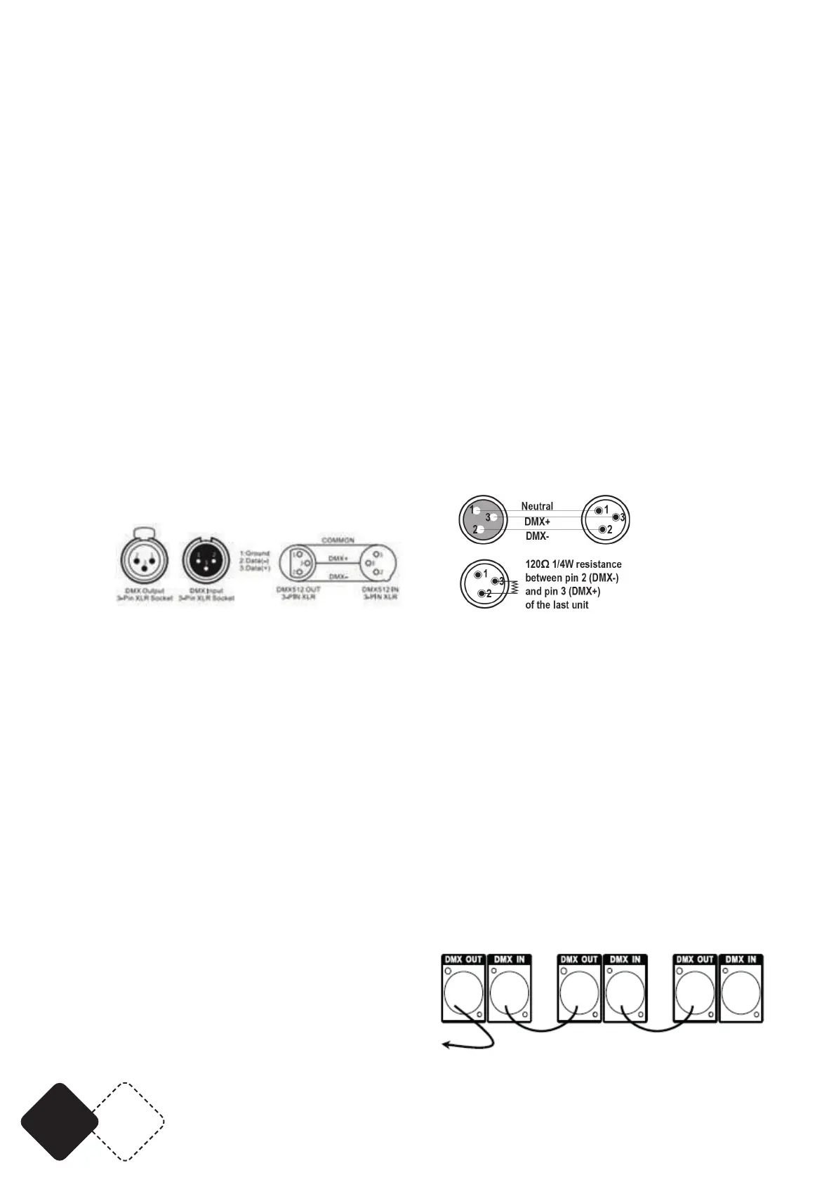
CABLE CONNECTORS
Cabling must have a male XLR connector on one end and a female XLR connector on the other end.
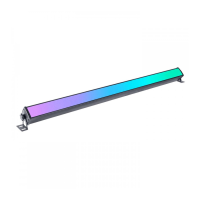
DMX connector conguration
Termination reduces signal errors. To avoid signal transmission problems and interference, it is
always advisable to connect a DMX signal terminator.
POWER LINK
You can power up to 5 units via the POWER IN/POWER OUT connectors from one single mains out-
let. Connect a POWERCON cable from the POWER OUT connector of the 1st unit to the POWER IN
connector of the second unit, etc.
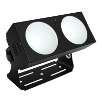
Setting up a DMX Serial Data Link
1. Connect the (male) 3 pin connector side of the DMX cable to the output (female) 3 pin connector
of the controller.
2. Connect the end of the cable coming from the controller which will have a (female) 3 pin
connector to the input connector of the next xture consisting of a (male) 3 pin connector.
3. Then, proceed to connect from the output as stated above to the input of the following xture
and so on.
Master/Slave Fixture Linking
1. Connect the (male) 3 pin connecter side of the
DMX cable to the output (female) 3 pin connecter
of the rst xture.
2. Connect the end of the cable coming from
the rst xture which will have a (female) 3 pin
connecter to the input connecter of the next xture