SEE FIGS. 1, 2, 3 & 4
The flue system must be installed in accordance with the
regulations in force.
Products of combustion discharge is by a fan powered
flue pipe of 50mm diameter which can reach up to 6
metres in length through a maximum of 6 x 90° bends or
9 metres with one bend. Exits from the appliance can be
from rear LH or RH sides, from the rear centre or from the
underside (Figs. 3 & 4).
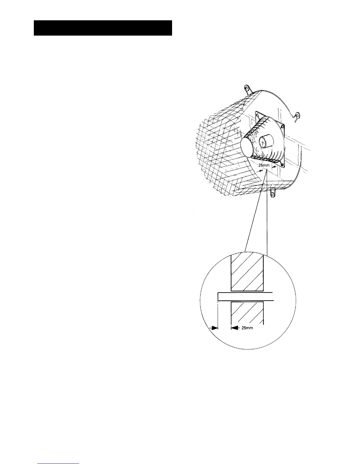
The flue pipe should exit through the outside wall fixing
plate by 25mm (Fig. 1).
Terminal Position
The minimum acceptable spacings from the terminal to
obstructions and ventilation openings are as shown in
Fig.2.
Where the terminal is fitted within 600mm below plastic
guttering an aluminium shield 1500mm long should be
fitted to the underside and immediately beneath the
guttering or eaves.
Where the terminal is fitted within 450mm below eaves or
painted guttering an aluminium shield 750mm long should
be fitted to the underside and immediately beneath the
guttering or eaves.
Terminal Protection
A terminal guard is supplied with the cooker and must be
fitted if flue termination is less than 2 metres above
ground level, or subject to damage.
When fitted, it must be positioned to provide a minimum
of 50mm clearance from any part of the terminal and be
central over the terminal.
4
FLUE SYSTEM
FIG.1
DESN 511189
DESN 511196
EXTERNAL
WALL