INSTALLATION
Check the appliance is electrically safe and gas sound when you have nished.
39
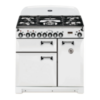
Stick on label
Stick the “NOW ADJUSTED FOR LP GAS” label next to the
ratings label inside the drawer cavity to indicate the gas the
appliance is now set for (Fig.8-12).
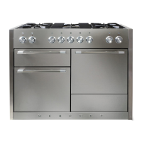
Pressure Testing
Connect the appliance to the gas supply. Check the appliance
is gas sound.
The gas pressure can be measured at the pressure test point
on the appliance side of the pressure regulator (Fig.8-13).
For proper operation, the pressure of LP supplied to the
regulator must be between 10’’ and 13’’ of water column
(2.49 - 3.24 kPa).
When checking for proper operation of the regulator, the
inlet pressure must be at least 1’’ (0.25 kPa) greater than the
operating (manifold) pressure as given above.
The pressure regulator located at the inlet of the range
manifold must remain in the supply line regardless of
whether natural or LP gas is being used.
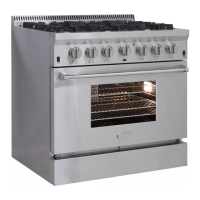
ArtNo.102-0008 - Regulator cap
ArtNo.102-0010 - Adjusted to LP gas label
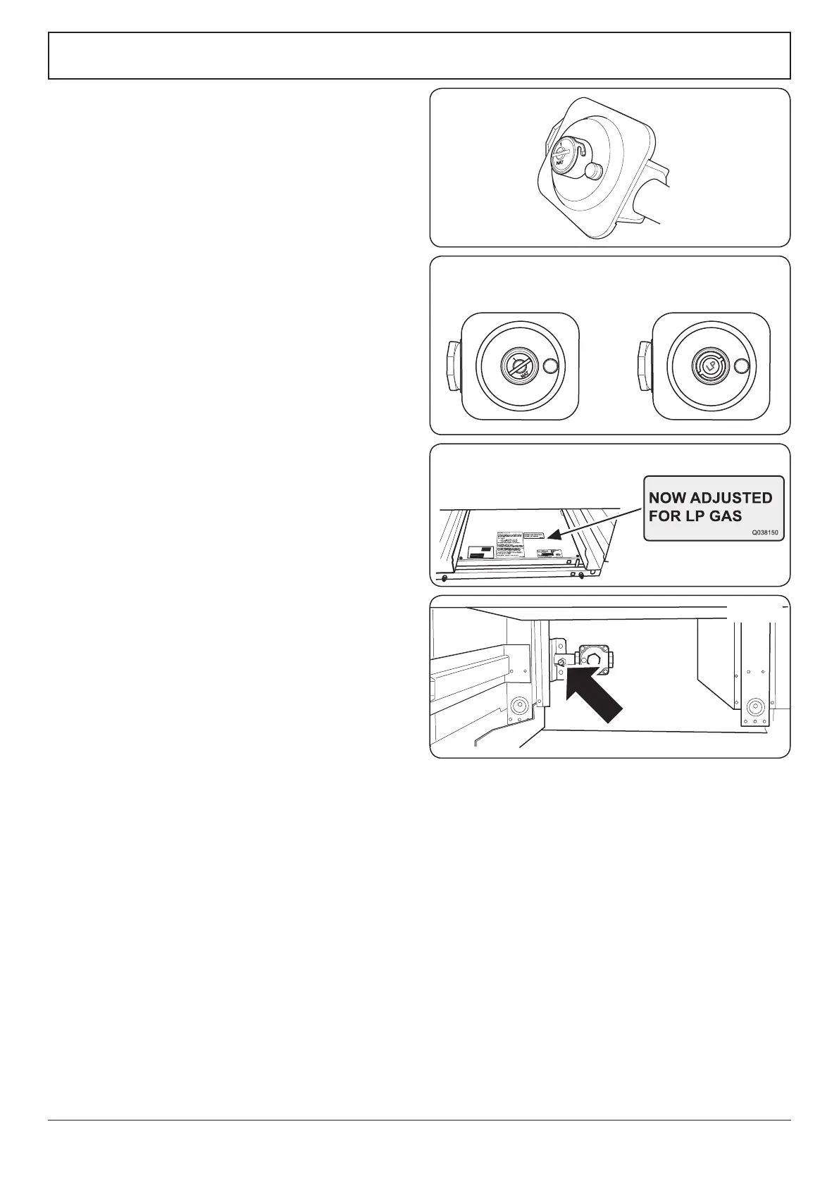
ArtNo.102-0009 - Gas regulator settings
Type 1 Type 2
Fig.8-10
Fig.8-11
Fig.8-12
ArtNo.102-0011 - Pressure test point
Fig.8-13