DX- D 600
User Manual
0242F EN 20181218
57
SECTION 4 CEILING SUSPENSION OPERATION
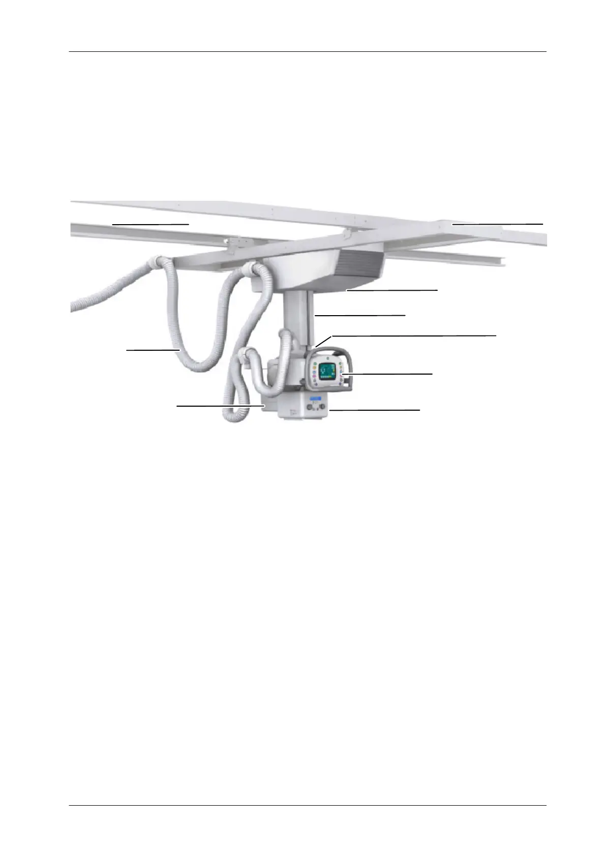
Illustration 4-1
Ceiling Suspension Nomenclature
Emergency-OFF Switch (Automatic Model)
Control Console
Longitudinal Rails
Collimator
Hose
L-block
Telescopic Column
Carriage
Transverse Rails
RAIL SYSTEM
The Rail System is formed by two pairs of rails made of aluminum and available
in different lengths (refer to Section 1.2). The rails allow the displacement of the
Carriage along the Longitudinal and Transverse Axis.
Longitudinal Rails or Axis (X), different lengths extrusion bars which fix the
Ceiling Suspension to the ceiling. They are marked with green color strips to
match the Brakes Buttons of the Control Console.
T ransverse Rails or Axis (Y), an horizontal structure fixed to the Longitudinal
Rails by two bearings assemblies that allow the movement along the
Longitudinal Rails. The bearings maintain also the alignment of the Transverse
Rails with the RAD Table. They are marked with orange color strips to match
the Brakes Buttons of the Control Console.
The system may be provided with a Cable Support Rail, an unistrut rail with the
same length of the Longitudinal Rails, located behind the back Longitudinal
Rail.