34980A Getting Started Guide 3
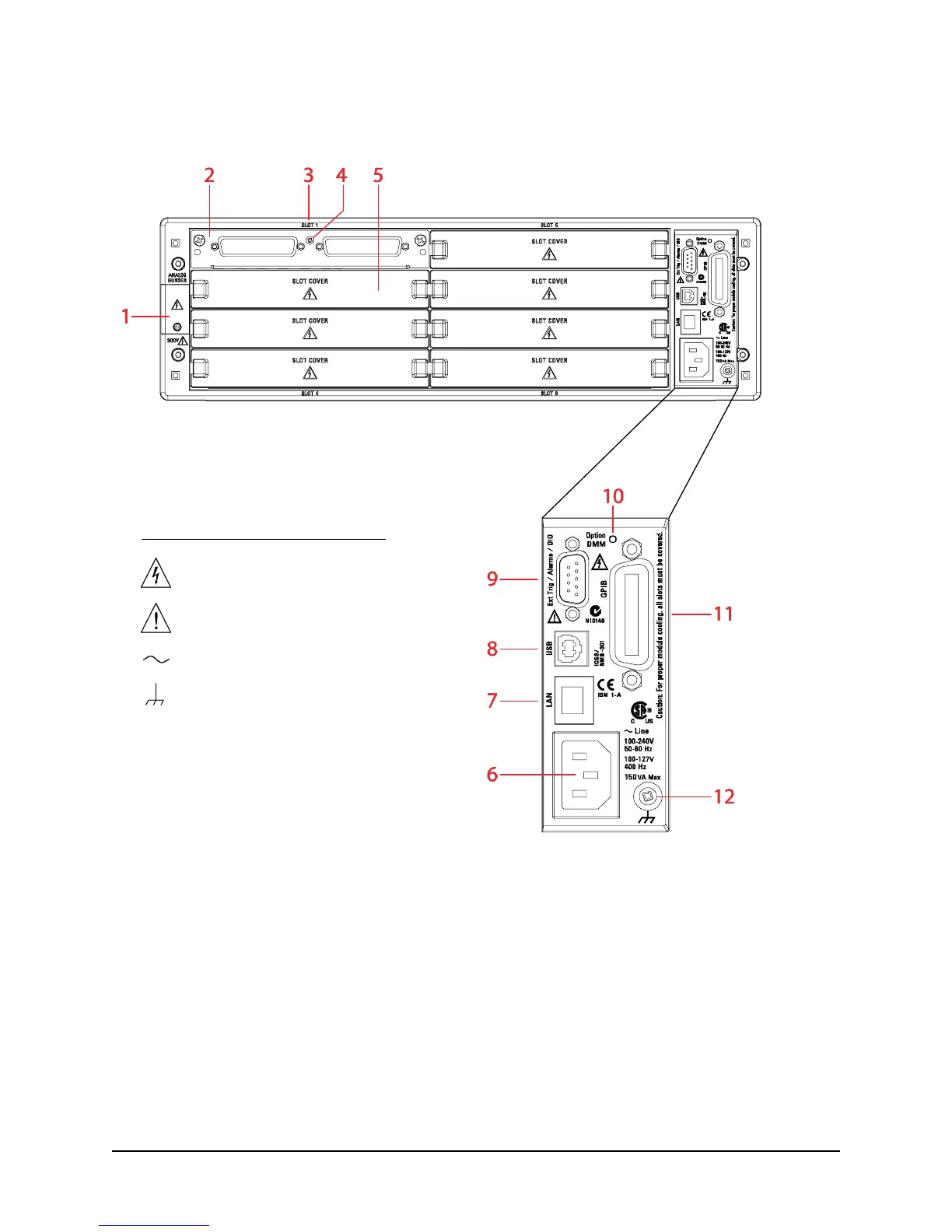
Rear Panel at a Glance
1 Access to Analog Buses (shown with cover installed). See 34980A
User’s Guide
for connector pinout.
2 Module shown installed in Slot 1
3 Slot Identifier (slots are numbered 1 through 8)
4 Module Chassis Ground Screw
5 Slot Cover
6 AC Power Connector
7 LAN Connector (10BaseT/100BaseTx)
8 USB 2.0 Connector
9 External Trigger/Alarm/Digital I/O Connector. See 34980A
User’s Guide
for connector pinout.
10 Internal DMM Option Marking. If you ordered the internal DMM option, this circle is marked black.
11 IEEE 488.2 GPIB Connector
12 Mainframe Chassis Ground Screw
Safety Symbols Located on Rear Panel
Warning, risk of electric shock
Caution, refer to accompanying
description
Alternating Current
Frame or chassis terminal
Safety Symbols Located on Rear Panel:
Warning. Risk of electric shock.
Caution. Refer to accompanying
description.
Alternating current.
Mainframe chassis ground.
 Loading...


