3-4
Testing Performance
To construct the test connector
To construct the test connector
The Agilent 54621D/22D Mixed-Signal Oscilloscope has digital channels that
you will need to connect to test equipment during testing. To easily connect the
digital channels, you will construct a test connector only if the 01660-63801
Test Fixture is not available.
Table 3-1
Materials Required to Construct the Test Connectors
1
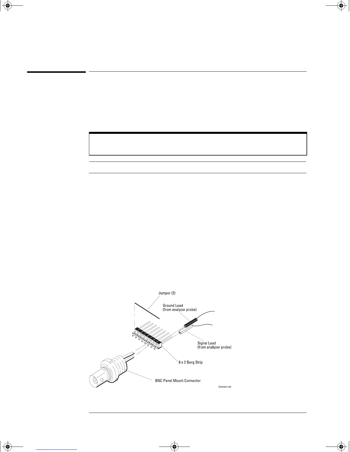
Obtain a BNC connector and an 8-by-2 section of Berg strip.
2 On one side of the Berg strip, solder a jumper wire to all of the pins.
3 On the other side of the Berg strip, solder another jumper wire to all of
the pins.
4 Solder the center of the BNC connector to a center pin on one of the
rows on the Berg strip.
5 Solder the ground tab of the BNC connector to a center pin on the other
row on the Berg strip.
Figure 3-1
Constructing the 8-by-2 Connector
Construct Test Connector only if Test Fixture is not available
The test connector is not required if 01660-63801 Test Fixture is available.
Description Recommended Part Qty
BNC (f) Connector Agilent 1250-1032 1
Berg Strip, 8-by-2 1
Jumper wire
service.book Page 4 Wednesday, December 18, 2002 8:35 AM
 Loading...


