5-7
Troubleshooting
To construct your own dummy load
To construct your own dummy load
1 Obtain a connector that is compatible with the connector J3 on the Low
Voltage Power Supply.
2 Connect load resistors to the connector as follows:
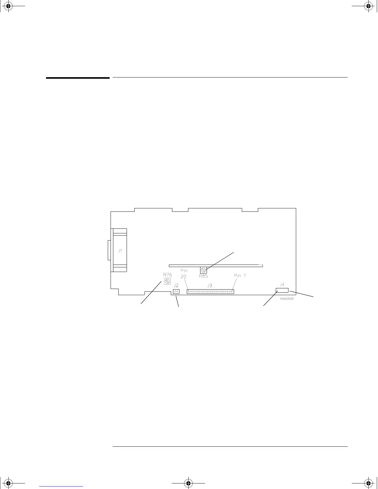
Figure 5-1
Location of the Low Voltage Power Supply Connectors
Connector Load (Amps) Resistor Watts Connect to Pin Ground to Pin
+5.1 V 4.4 A 1.2 Ω 22 W 10, 11, 12 13, 14
-5.2 V 1.6 A 3.25 Ω 8 W 4, 5 6
+15.75 V 1.2 A 13.1 Ω 20 W 1 2
+3.3 V 4 A 0.825 Ω 13 W 15, 16, 17, 18 19, 20
+5.1 / -5.2 V
Balance Adjustment
E2 and E3
8.5 V DC
Fan Connector Printer Power
+3.3V Adjustment
service.book Page 7 Wednesday, December 18, 2002 8:35 AM
 Loading...


