4-5
Calibrating and Adjusting
To adjust the power supply
2
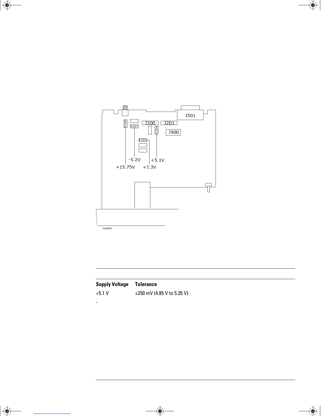
Locate the power supply voltages at E204, E205, E207, and E208 on the
system board.
The power supply voltages are not labeled on the system board. See
Figure 4-1 for the locations.
Figure 4-1
Low Voltage Power Supply Voltages (on the bottom of the oscilloscope)
3 Make sure that the voltage measurements are within the tolerances
listed in Table 4-2.
Table 4-2 Power Supply Voltage Tolerances
-
-
- -
9
(
(
(
(
9
9
9
Supply Voltage Tolerance
+5.1 V ±250 mV (4.85 V to 5.35 V)
-5.2 V ±156 mV (-5.04 V to -5.36 V)
+15.75 V +1.260 V, -787 mV (+14.963 V to +17.010 V)
+3.3 V ±100 mV (+3.20 V to +3.40 V)
+8.2 V ±82 mV (+8.12 V to +8.28 V)
measure at J4 on the power supply board
service.book Page 5 Wednesday, December 18, 2002 8:35 AM
 Loading...


