144 Diagrams
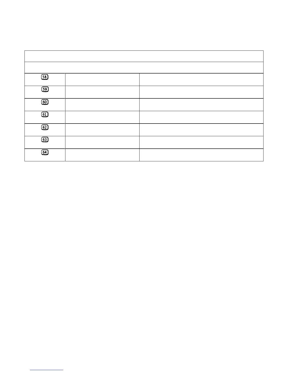
Table 6-3. Test Points (continued)
A4A2/A4A4 RIGHT TUNNEL BOARDS (FIGURE 6-7)
The same measurement conditions apply as were described for the A4Al/A4A3 Left Tunnel Boards.
U301-3
OUTPUT CONTROL 0.03V (6651-54), 0.06 V (6655) in CV mode
0.6V in CC mode
U301-2
Stage 1 comparator-input 0.03V (6651-54), 0.06 V (6655) in CV mode
0.06V in CC mode
U301-1
Stage 1 FET driver control 4V in CV mode
4.7V in CC mode
†Q302-3
Stage 1 reg control 0.6V in CV mode (reg Q301 on)
1.3V in CC mode (reg Q301 on)
U302-2
Stage 4 comparator-input 0.17V in CV mode
4.4V in CC mode
U302-1
Stage 4 FET driver control - 12V in CV mode
4.4V in CC mode
†Q308-3
Stage 4 reg control 0V in CV mode (reg Q307 off)
1.2V in CC mode (reg Q307 on)
† Models 65/6651-65/6654 only (Not used on 120 V units).
 Loading...


