Appendix A
LOGIC SYMBOLOGY
The logic symbols used in this manual are based on
ANSI/IEEE Std 91-1984 (or later), which is a revision of
ANSI Y32.14. The following paragraphs and illustrations
provide a brief description of the symbology to aid in
interpreting the symbols. When referring to the symbols, it
should be remembered that:
1. Power supply and ground connections usually are not
shown on the symbols, but are listed separately on the
schematic.
2. Items in brackets [ ] are not part of the symbol, but are
included to help the user interpret the symbol.
3. Unless arrows indicate otherwise, inputs are on left,
outputs are on right, and signal flow is from left to
right.
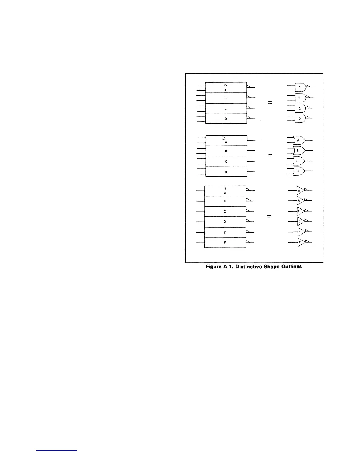
4. In an array of two or more identical elements, only the
first (top) element is shown in full detail.
5. When shown individually on a schematic rather than as
part of an array, basic logic gates (AND, OR, buffer) are
shown by distinctive-shape outlines (see Figure A-1).
Qualifier and Functional Labels.FigureA-1 shows qualifiers
and functional labels. Qualifiers denote basic logic function.
For example, "&" denotes the AND function. Functional
labels, such as DEMUX for a demultiplexer, identify
complex devices.
A-1
 Loading...


