Introduction
Chapter 14
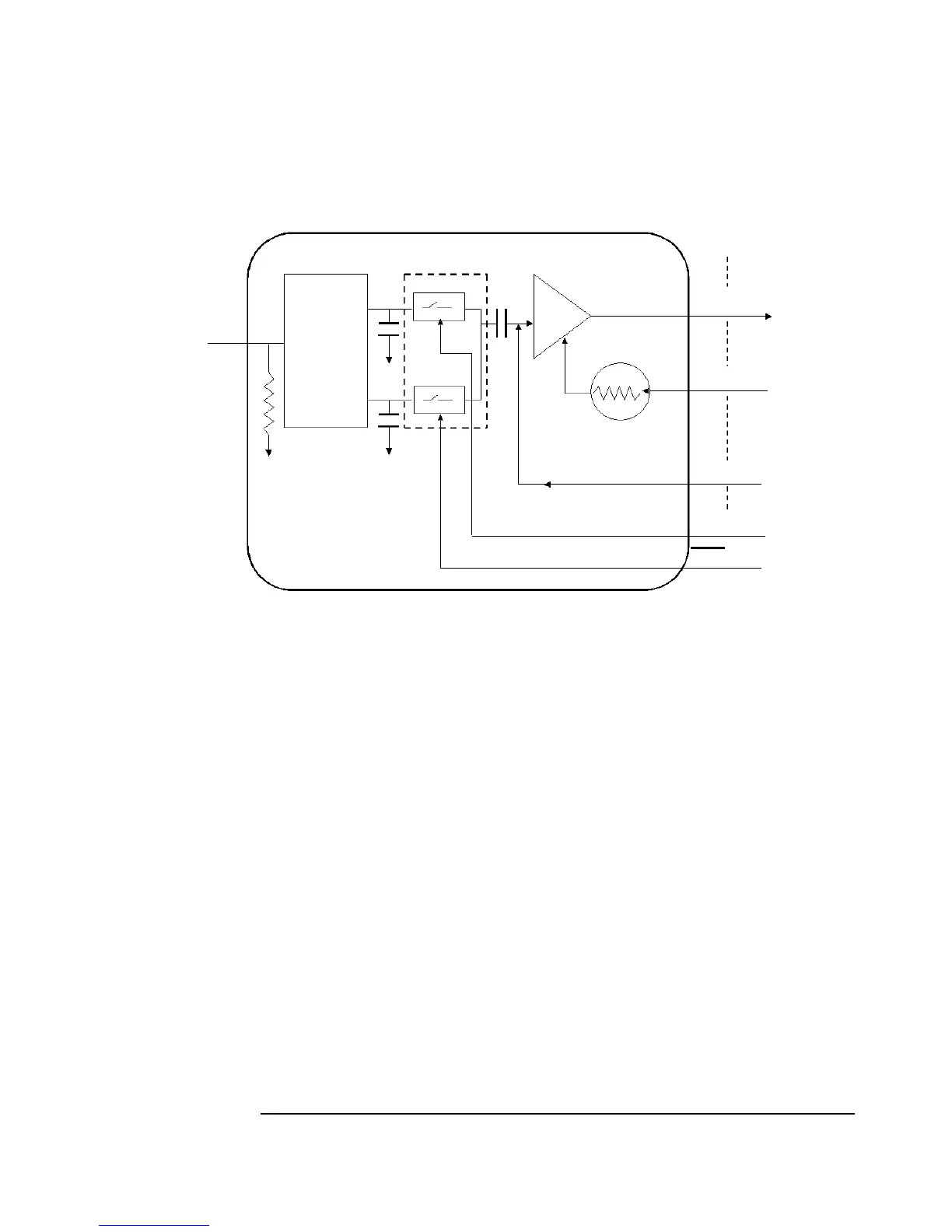
Figure 1-2 8480 Series Power Sensor Simplified Block Diagram
Figure 1-2 shows a basic power sensor block diagram for both thermocouple and
diode power sensing elements. From the RF or microwave signal input, both
thermocouple and diode detector mounts generate very low voltages, (on the order
of nV or µV). The dc voltage is proportional to the power from the RF or microwave
source. As the dc voltage is a very low-level, it requires amplification before it can
be transferred to the power meter on the standard cables.
The amplification is provided by an input amplifier assembly that consists of a
balanced chopper (sampling gate) and an AC coupled low-noise amplifier. The dc
voltage is routed on gold wires to the chopper circuit, which converts the low-level
dc voltage to an ac voltage. To do this, the chopper is uses two field effect transistors
(FET's) controlled by a 220 Hz square-wave generated by in the power meter (the
Chop Signal). The result is an ac output signal proportional to the dc input. The ac
signal is then amplified to a relatively high-level ac signal that can be routed to the
power meter by standard cables.
The autozero signal removes residual error voltages when there is no input RF or
microwave power connected to the sensor input, and temperature compensation is
provided by a thermistor located in amplifier feedback path.
Input
Power
Sensing
Element
Thermocouple
or Diode
Balanced Chopper
Thermistor
Cable
AC Signal
Feedback
Chop Signal
Chop Signal
Autozero