Service
Chapter 3 41
If the resistance value is incorrect (failure is usually indicated by an open circuit),
then the A1 Bulkhead Assembly is defective. If the resistance is correct then
continue to test the A2 Power Sensor Board Assembly.
A1 Bulkhead (Diode Sensors)
CAUTION Disconnect the gold wires from the A2 assembly before measuring the voltage. Be
extremely careful when measuring across the gold wires. They are delicate and can
be damaged easily.
Step 1. Disconnect all cables from the Power Sensor.
Step 2. Remove the clamp holding the two gold wires.
Step 3. Connect the Precision 30dB Attenuator to the 1mW Power Reference connector on
the power meter.
Step 4. Connect the Power Sensor to the Precision 30dB Attenuator.
NOTE Models 8485A and 8487A require 3.5mm and 2.4mm adapters respectively.
Step 5. Turn on the 1mW Power Reference, and measure the voltage across the two gold
wires. The voltage should be between 0.9mV and 1.5mV. If the voltage is incorrect,
then the A1 Bulkhead Assembly is defective. If the voltage is correct then continue
to test the A2 Power Sensor Board Assembly.
A2 Power Sensor Board Assembly
It is extremely rare for the A2 Assembly to fail. Eliminate the power meter, the
sensor cable, and the A1 Bulkhead Assembly before suspecting the A2 Assembly.
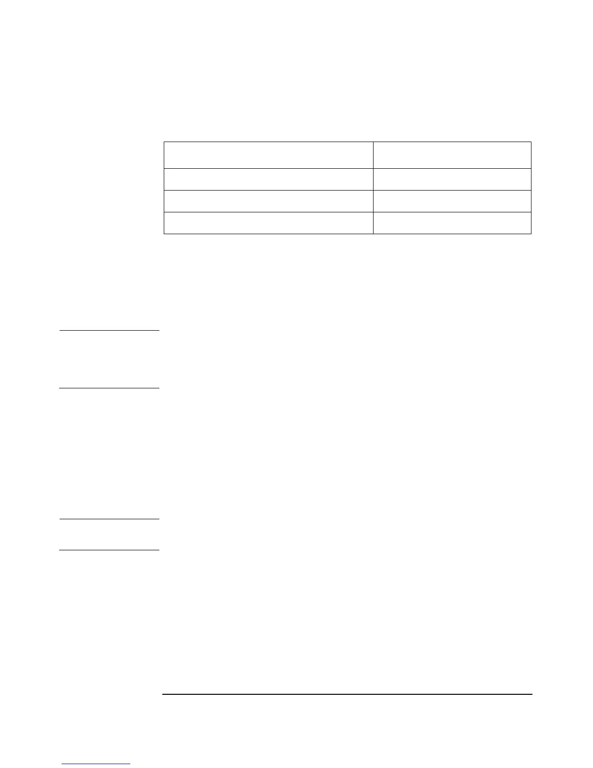
Table 3-1 Bulkhead Assembly Resistance
Model Measured Resistance
8481A, 8481B, 8481H, 8485A, 8487A: 200 Ohms ± 10 Ohms
8482A, 8482B, 8482H: 245 Ohms ± 12.5 Ohms
8483A: 375 Ohms ± 17.5 Ohms