Chapter 3 127
Manual Adjustment Procedures
4. Sampling Oscillator Adjustment
Procedure
1. Press LINE to turn the spectrum analyzer off and disconnect the line
power cord. Remove the spectrum analyzer cover and fold down the
A15 RF and A14 frequency control assemblies. Prop up the A14
frequency control assembly. Reconnect the line power cord and press
LINE to turn the spectrum analyzer on. Connect the equipment as
illustrated in Figure 3-11 on page 126.
2. Press PRESET on the spectrum analyzer and set the controls as
follows:
Center frequency ................................................ 2126MHz
Span ..............................................................................0Hz
3. Set the 3456A controls as follows:
Function .............................................................DCVOLTS
Range .......................................................... 10V,MANUAL
Sampling Oscillator Adjustment
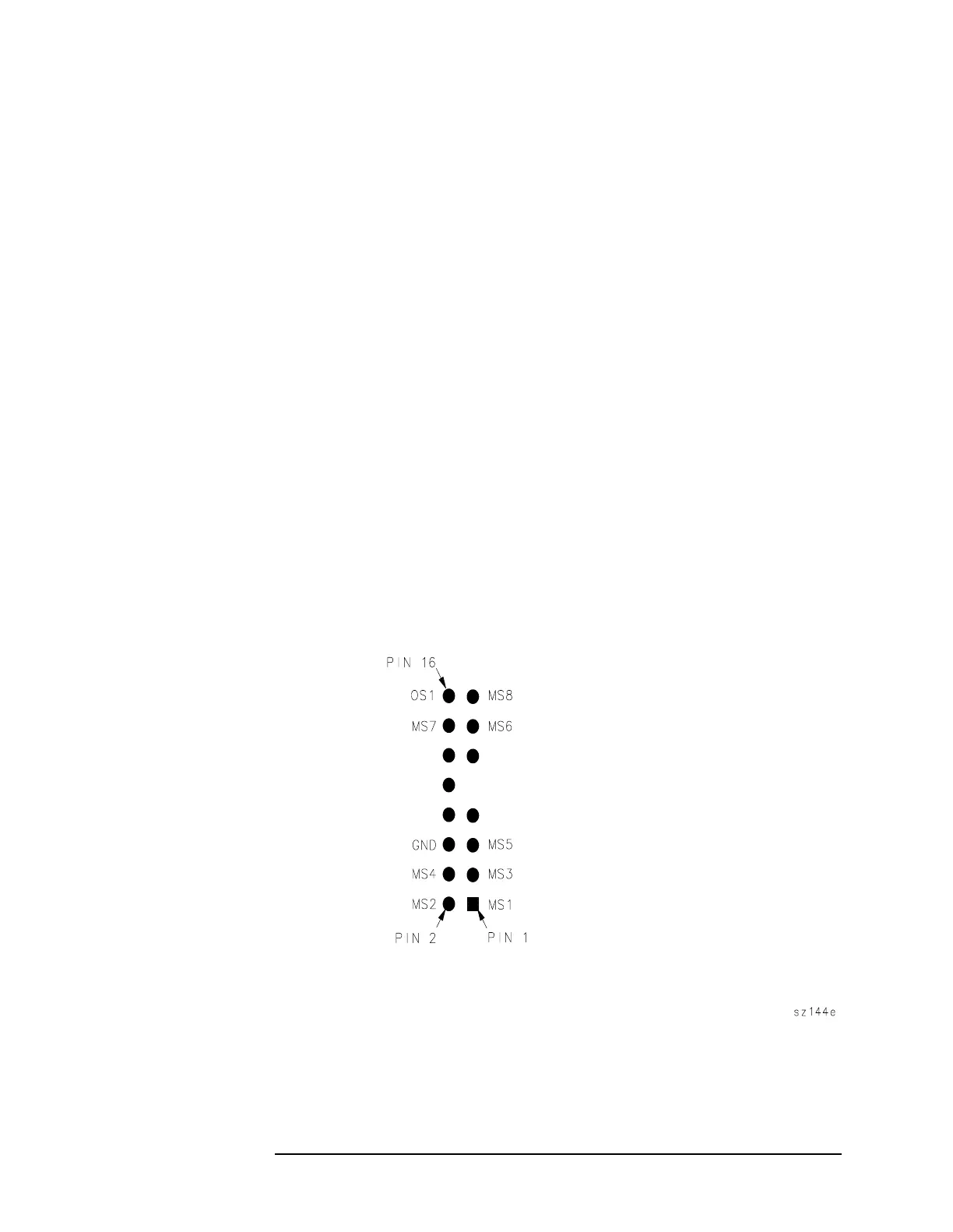
1. Connect the negative DVM test lead to A15J200 pin 6. Connect the
positive DVM lead to A15J200 pin 13.
2. Adjust A15C210 VCO RANGE for a DVM reading of 5.05 V ±0.05 V.
Figure 3-12 A15J200 Pin Locations
 Loading...


