Chapter 11 531
Synthesizer Section
Confirming a Faulty Synthesizer Section
17.Tune the source 1 kHz above the fractional N frequency. The voltage
measured on the DVM should be approximately −12 Vdc.
18.If the DVM reading does not change, the A14 frequency control
assembly is defective. Reconnect W32 to A14J501. Replace the
jumper on A14J23 to the NORM position.
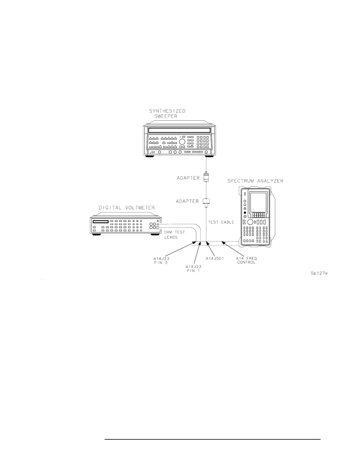
Figure 11-3 YTO Loop Test Setup
Check A15 RF
assembly (steps
19-25)
19.Disconnect W34 from A15U100J1 and disconnect W32 from
A15J101.
20.Connect a frequency counter to A15J101. Connect a high-frequency
test cable from an 8340A/B synthesized sweeper to A15U100J1. See
Figure 11-4 on page 532.
21.Connect a BNC cable from the spectrum analyzer 10 MHz REF
IN/OUT to the 8340A/B FREQUENCY STANDARD EXT input.
22.Set the 8340A/B to the following settings:
Frequency standard ........................................................EXT
Power level ................................................................. −5dBm
23.Set the spectrum analyzer to the following settings:
Span ..............................................................................0Hz
Trigger ...................................................................SINGLE
 Loading...


