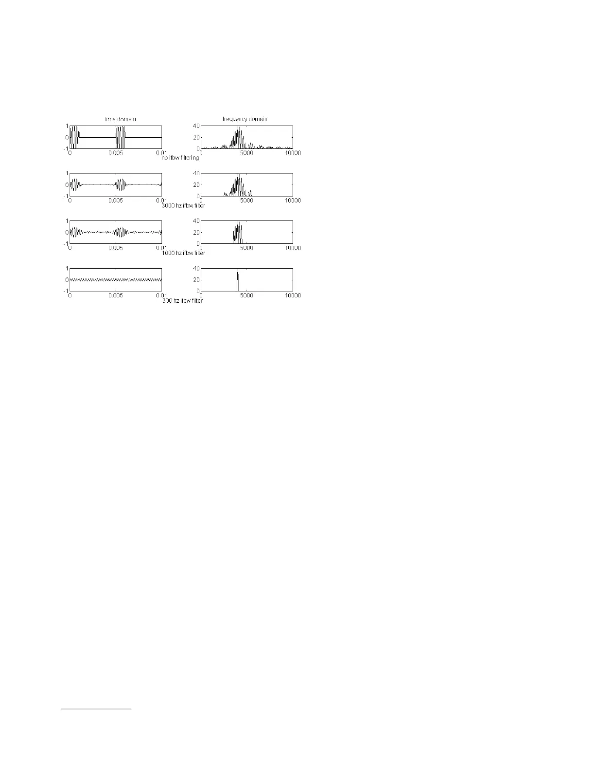
The second pair of diagrams in Figure 2 shows the effect
of a 3000 Hz IF bandwidth filter on the pulse. Notice
that many of the sidebands have been eliminated. Notice
also what has happened to the shape of the pulse in the
time domain.
Figure 2. Effect of IF filtering on high PRF measurements
The third pair of diagrams in Figure 2 shows the effect
of a 1000-Hz IF bandwidth filter on the pulse. Only a few
spectral lines will fit within the bandwidth of the IF
bandwidth filter. We know that there are an infinite
number of spectral lines in the spectrum of any rectan-
gular pulse; if we filter off all but a few of them with our
IF bandwidth filter, what has that done to the shape of
the pulse? Look at the corresponding diagram in the left
column. The pulse is becoming rounded and smoothed,
so that it no longer has a definite beginning or end.
Some signal is always present. Since a high PRF pulse is
by definition too narrow for external triggering to be
effective, the analyzer responds to this signal as though
the S-parameter of the DUT is continuously varying as
the pulse amplitude varies. Clearly, this is an undesirable
operating condition.
The fourth pair of diagrams in Figure 2 shows the effect
of a 300-Hz IF bandwidth filter on the pulse. At this nar-
row IF bandwidth, only a single spectral line will fit with-
in the filter bandwidth
1
, and the pulse appears as a
single, continuous frequency, but at a lower power level.
Since this is the normal operating condition for a net-
work analyzer, the analyzer responds normally, except
that we must account for the diminished power level.
The magnitude decrease in the central spectral line is
logarithmically proportional to the duty cycle of the
pulse. This decrease is called pulse desensitization, and
the formula for computing it is:
Pulse Desensitation ≡ 20
*
Log(Duty Cycle)
The reason pulse desensitization occurs is because the
energy of the pulse is spread throughout the spectrum,
in all the sidebands. Since we have removed all the side-
bands and retained only the central spectral line, we
have discarded a large fraction of the available energy. In
the 8510C, pulsing both the measurement channel and
the reference channel can eliminate pulse desensitiza-
tion. The 8720ES cannot operate with a pulsed refer-
ence channel because it has only a single reference
channel that requires a continuous signal to phase lock
the source to the receiver. This is also true for the
8720ES Option 400 (four samplers for true TRL calibra-
tion). Despite the fact that this instrument does contain
separate reference channels, its hardware and firmware
are not designed to allow them to be configured individ-
ually.
When making high PRF measurements, the 8720ES is
limited on the low end to a PRF of 20 or greater. This is
because the narrowest IF bandwidth for this analyzer is
10 Hz, and it has been found experimentally that the
PRF should be at least twice the IF bandwidth for high
PRF measurements. For a PRF below 20 Hz, the IF filter
includes multiple spectral lines, and we are forced to use
the techniques described for low PRF measurements.
On the high end of the PRF scale, this analyzer is limited
by duty cycle. Once the dynamic range is reduced below
about 30 dB, most measurements become impractical.
Since the dynamic range of the analyzer is reduced
directly by the amount of pulse desensitization, this
point is usually reached when the duty cycle drops
below approximately 0.001
Finally, in order to be measured properly using the
8720ES, the pulse width must be wider than approxi-
mately 500 nanoseconds. Below this pulse width, it is
difficult to ensure that the requirements for a rectangu-
lar pulse are being met. Once the pulse begins to distort,
the technique used to extract the central spectral line
becomes unreliable. Practically speaking, this limits the
maximum PRF to about 2 MHz.
Specialized pulse analyzers such as the 85108A use
wideband detection, and so are able to capture a large
proportion of the available energy in each pulse. This is
an advantage because it permits measurements at very
low duty cycles with very little reduction in dynamic
range.
5
1. This is true because this is a perfect mathematical model, so the IF bandwidth filter is perfectly centered on the spectral line. In a real analyzer, the filter could be
far enough off center to capture two spectral lines.
 Loading...


