Chapter 7 Tutorial
Overview of this Power Supply Operation
151
7
Overview of this Power Supply Operation
The basic design model for power supplies consists of placing a control element in
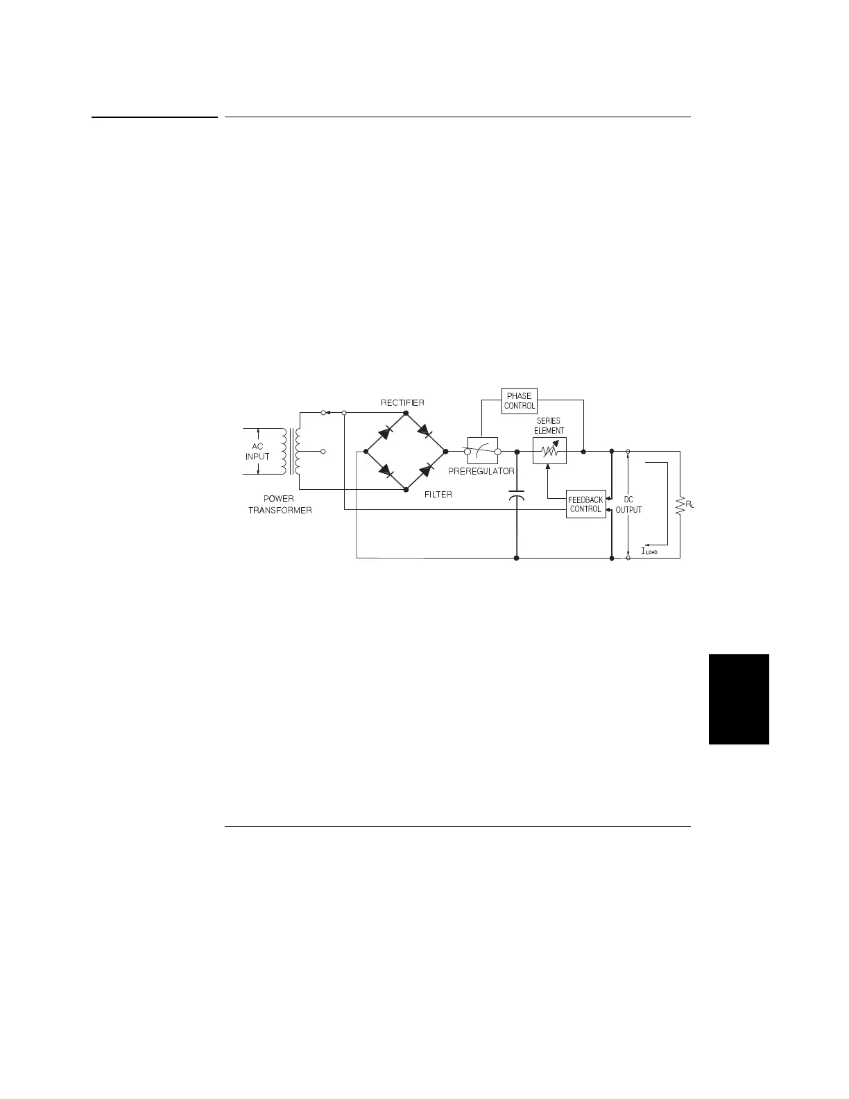
series with the rectifier and load device. Figure 7-1 shows a simplified schematic of
a series regulated supply with the phase-controlled pre-regulator described as a power
switch and the series element depicted as a variable resistor. The phase-controlled
pre-regulator minimizes the power dissipated at the series element by maintaining the
voltage drop across the series element at a low and constant. Feedback control circuits
continuously monitor the output and adjust the series resistance to maintain a constant
output voltage. Because the variable resistance of Figure 7-1 is actually one or more
power transistor operating in the linear (class A) mode, supplies with this type of
regulator are often called linear power supplies. Linear power supplies have many
advantages and usually provide the simplest most effective means of satisfying high
performance and low power requirements.
Figure 7-1. Diagram of Simple Series Power Supply
This power supply has two ranges, allowing more voltage at a lower current or more
current at a lower voltage. Single range supplies can only output maximum power at
full scale voltages and full scale current. This supply can provide output power that
is close to maximum at full scale for both ranges. The pre-regulator in this power
supply uses solid state transformer tap switches on the secondary winding of the power
transformer. This technique is very effective in reducing the power dissipated in the
series element.
 Loading...


