Appendix Service Information
Troubleshooting Hints
175
Service
Information
Troubleshooting Hints
This section provides a brief check list of common failures. Before troubleshooting
or repairing the power supply, make sure that the failure is in the power supply rather
than any external connections. Also make sure that the power supply is accurately
calibrated. The power supply’s circuits allow troubleshooting and repair with basic
equipment such as a 6½-digital multimeter.
Unit Reports Errors 740 to 750
These errors may be produced if you accidentally turn off power of the unit during a
calibration or while changing a non-volatile state of the instrument. Recalibration or
resetting the state should clear the error. If the error persists, a hardware failure may
have occurred.
Unit Fails Self-Test
Verify that the correct power-line voltage setting is selected. Also, ensure that all
terminal connections are removed while the self-test is performed. Failure of the DAC
U20 on the PC board will cause many self-test failures.
Bias Supplies Problems
Check that the input to the voltage regulators of the bias supplies is at least
1 V greater than their output. Circuit failures can cause heavy loads of the bias supplies
which may pull down the regulator output voltages. Check the voltages of bias
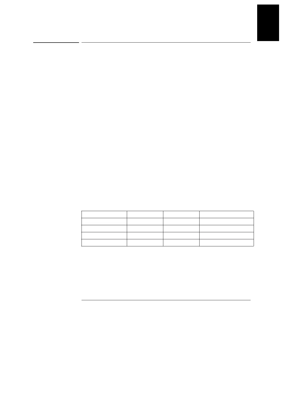
supplies as tabulated below.
Table A-1 Bias Supplies Voltages
Some circuits produce their own local bias supplies from the main bias supplies. Be
sure to check that these local bias supplies are active. In particular, the ADC (analog-
to-digital converter), ac input, and front panel sections have local bias supplies.
Always check that the power supplies are free of ac oscillations using an oscilloscope.
Failure of bias supplies will cause many self-test failures.
Bias Supply Minimum Maximum Check At
+5V Floating +4.75 V +5.25 V U14 pin 2
-5.1V Floating -4.75 V -5.25 V Anode of CR15
+15V Floating +14.25 V +15.75 V Anode of CR139
-15V Floating -14.25 V -15.75 V Cathode of CR140
 Loading...


