Chapter 4 107
Troubleshooting the RF Section (E4446A, E4447A, E4448A)
RF Section Description (E4446A, E4447A, E4448A)
A13 Front End Driver
The Front End Driver assembly contains the circuitry needed to drive
the microcircuits and other assemblies used in the RF section. Many of
these circuits can be verified using the previous discussions for
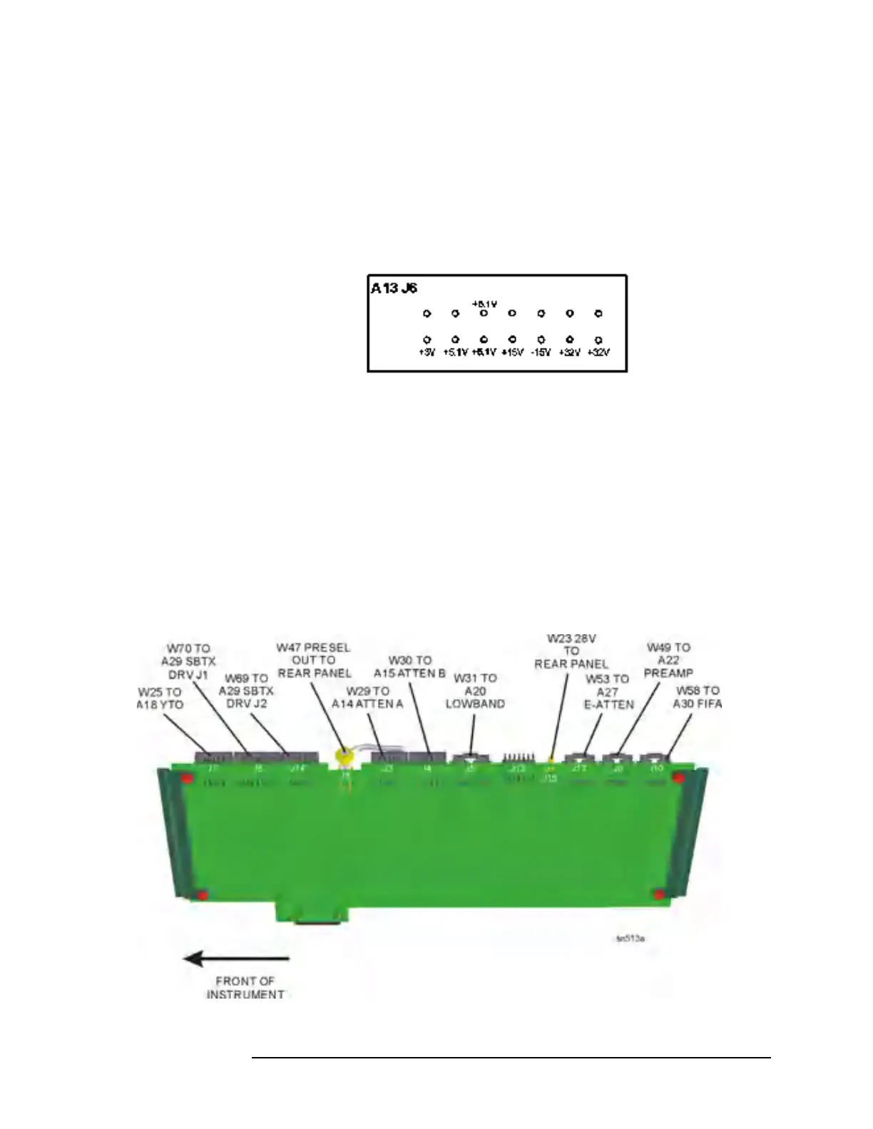
verifying these assemblies. The voltage values on selected connectors
are (with ground connection on A13TP16 top of board near fans):
Option 219, Noise Figure, provides a switched 28V (via A13J15) to the
rear panel to drive a noise source. Press
System, Serv ice , enter the
password −49, and press
Service, Noise Source to turn on the 28V at
J15. This 28V is the result of regulating the +32V power supply voltage
on the Front End Driver assembly. If the 28V cannot be turned on or is
not 28V ± 0.2V, suspect the Front End Driver or a power supply
problem. The RF input attenuator also uses the +32V supply, so if the
attenuator also functions incorrectly, suspect an incorrect power supply
level.
Figure 4-8 Front End Driver Assembly - E4446A, E4447A, E4448A

 Loading...


