322 Chapter 11
Assembly Replacement Procedures
RF Section E4440A, E4443A, E4445A
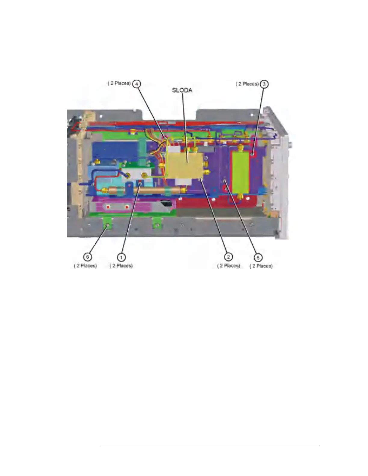
Figure 11-10 RF Section Hardware
A18 YTO and A19 RYTHM
Removal
1. Refer to Figure 11-9. Remove the semi-rigid cables, W9, W35, W36,
and W38.
2. Remove the ribbon cables attached to the YTO and RYTHM.
3. Refer to Figure 11-10. Using the T-10 driver, remove the 2 screws
(1). Remove the third screw that can be accessed down behind the
YTO, near the Mid Web.
4. Carefully remove the bracket containing the YTO and RYTHM from
the RF section.

 Loading...


