74 Chapter 3
Troubleshooting the RF Section (E4440A, E4443A, E4445A)
RF Section Description (E4440A, E4443A, E4445A)
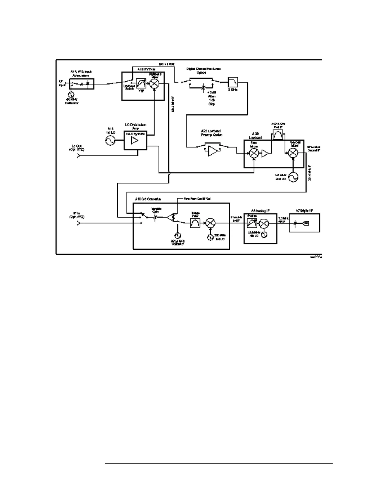
Figure 3-3 Block Diagram with RF Options - E4440A, E4443A, E4445A
Option BAB
(E4440A only) - APC 3.5 mm input connector. Standard PSAs use a
precision machined Type N connector for the RF input.
Option B7J - Digital Demod Hardware. The electronic attenuator
works over the lowband frequency range. In bypass
mode, the coax switches in the electronic attenuator
board route the RF signal on through to the Lowband
board. The electronic attenuator path consists a 40 dB,
1 dB step solid state attenuator.
Option 1DS - Low Band Preamp. In bypass mode, the coax switches
route the Low Band RF signal on to the Lowband
assembly. When in preamp mode the 30 dB gain, low
noise figure amplifier path is selected.
Option AYZ
(E4440A only) - External Mixing. Allows an external preselected or
unpreselected mm wave mixer to be used with the
instrument.

 Loading...


