Chapter 3 77
Troubleshooting the RF Section (E4440A, E4443A, E4445A)
RF Section Description (E4440A, E4443A, E4445A)
If the DC/AC Coupling modes are not properly functioning, a similar
table can be used.
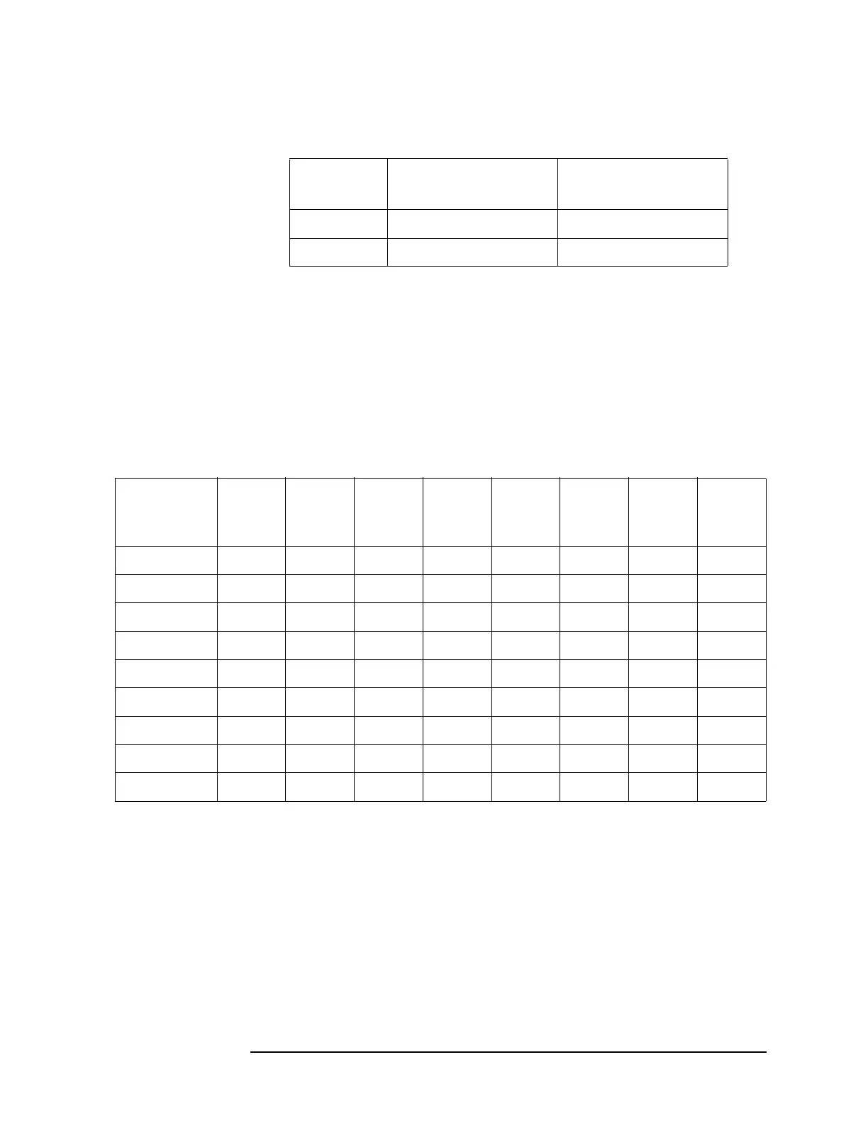
Improper displayed signal amplitudes in some attenuator settings can
be isolated to either A13 or A14 based on which steps are incorrect.
Signal out of the attenuators can be measured by disconnecting the
appropriate semirigid cable and using a spectrum analyzer. Referring
to Figure 3-4, A14 has two 2 dB sections and A15 has a 6 db, a 10 dB, a
20 dB and a 30 dB section. Verify that the attenuators are receiving the
correct switching sequences by using the following tables.
Coupling DC Block Select
J3 pin 9
DC Block Bypass
J3 pin 4
DC High Low
AC Low High
Table 3-1 A15 Settings
Attenuation
(dB)
6 dB
Select
J4 pin 9
6 dB
Bypass
J4 pin 4
10 dB
Select
J4 pin 2
10 dB
Bypass
J4 pin 1
20 dB
Select
J4 pin 8
20 dB
Bypass
J4 pin 5
30 dB
Select
J4 pin 7
30 dB
Bypass
J4 pin 6
0 High Low High Low High Low High Low
6 Low High High Low High Low High Low
10 High Low Low High High Low High Low
20 High Low High Low Low High High Low
30 High Low High Low High Low Low High
40 High Low Low High High Low Low High
50 High Low High Low Low High Low High
60 High Low Low High Low High Low High
70 Low High Low High Low High Low High

 Loading...


