282 Chapter 5
Concepts
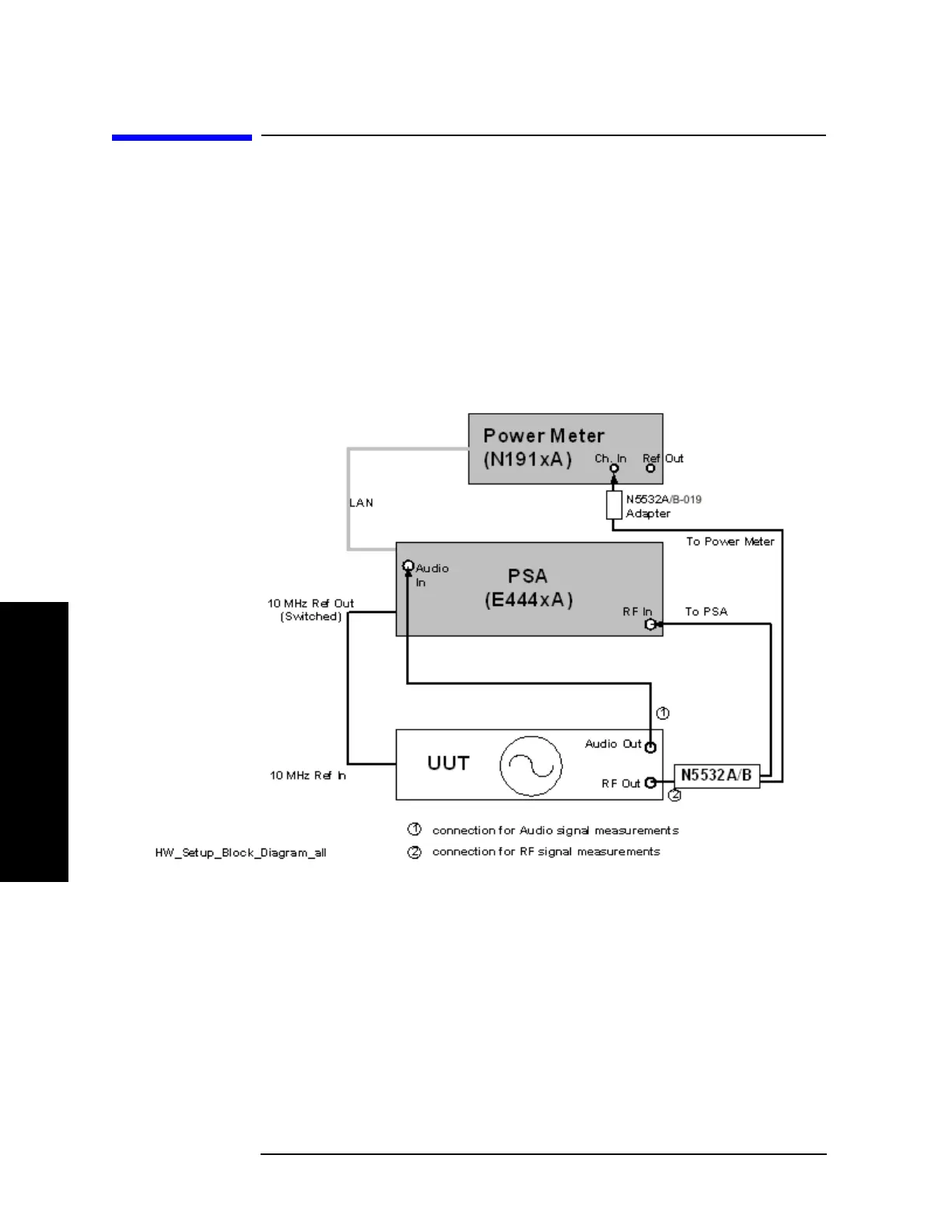
N5531S Block Diagram
N5531S Block Diagram
A block diagram of the N5531S Measuring Receiver System is shown below.
The system may consist of:
1. PSA Series Spectrum analyzer (PSA) (For specifications, refer to Table 2-1 on
page 41.)
2. P-Series Power Meter (For specifications, refer to Table 2-2 on page 41.)
3. N5532A/B Sensor Module (For specifications, refer to Table 2-3 on page 42.)
Figure 5-1 Block Diagram
The N5532A/B Sensor Module receives the incoming signal from the UUT and
splits it between the Power Meter and PSA. RF Power is measured by the Power
Meter, whereas all other measurements are performed using the PSA.

 Loading...