Service Guide E8364-90038 7-15
PNA Series Microwave Network Analyzers Repair and Replacement Procedures
E8362C, E8363C, E8364C Removing and Replacing Front Panel Subassemblies
Replacing the Touch Screen Display Assembly
1. Refer to Figure 7-4 and Figure 7-5 for this procedure.
2. Remove the A2 display assembly. Refer to the procedure on page 7-13.
3. Note the orientation of the touch screen display in the front panel frame. THIS IS VERY IMPORTANT. THE
NEW ONE MUST BE INSTALLED IN EXACTLY THE SAME ORIENTATION. Refer to Figure 7-5.
4. Carefully lift the touch screen display and remove it from the front panel assembly.
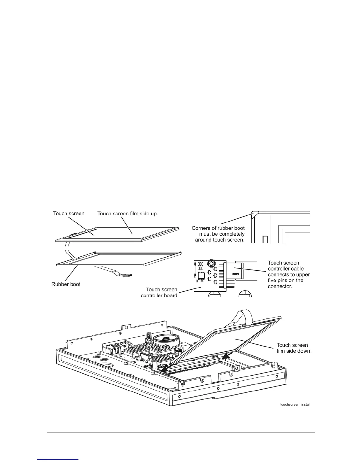
5. Note the orientation of the rubber boot surrounding the touch screen display. THIS IS VERY IMPORTANT.
THE BOOT MUST BE REINSTALLED EXACTLY AS IT WAS.
6. Remove the protective cover from the new touch screen then remove the rubber boot from the old touch
screen and install it on the new touch screen. Refer to Figure 7-5.
7. Install the new touch screen display and the A2 display by reversing the removal instructions. Refer to
Figure 7-5
.
REMEMBER, THE TOUCHSCREEN CONTROLLER CABLE CONNECTS TO THE UPPER FIVE PINS ON THE
CONTROLLER BOARD CONNECTOR.
8. Perform the post-repair adjustments, verifications, and performance tests that pertain to this
replacement procedure. Refer to Table 7-2 on page 7-82.
Figure 7-5 Touch Screen Display and Rubber Boot Installation
 Loading...


