14 Installation Note E8364-90024
Step 6. Install the Option 081 Reference Switches
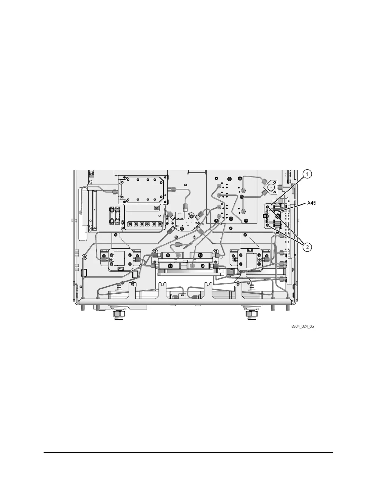
Install the A45 Reference Switch
Refer to Figure 9 for this procedure. The new parts referenced in this procedure are listed in
Table 1 on page 4.
1. Attach one of the reference switches (provided) to the mounting bracket (item
①)
(provided) using four M3.0 x 12 screws (provided).
2. Insert the bracket, with the A45 reference switch attached, into the location shown.
3. With a T-10 TORX driver, install two M3.0 x 6 mounting screws (item
②) (provided) in the
bracket to secure it to the test set deck.
Figure 9 A45 Reference Switch Installation
 Loading...


