5-4 Chapter 5
Making GSM Cable and Antenna Measurements
Making Cable Fault Location Measurements
b. Page through available cable types using the tab, RPG, or Step
keys.
c. Press the
Select menu key to select the appropriate cable type.
3. Set up a maximum range value just greater than the length of the
cable to be tested:
a. Press the
Max Range menu key.
b. Enter the appropriate value using the numeric key pad.
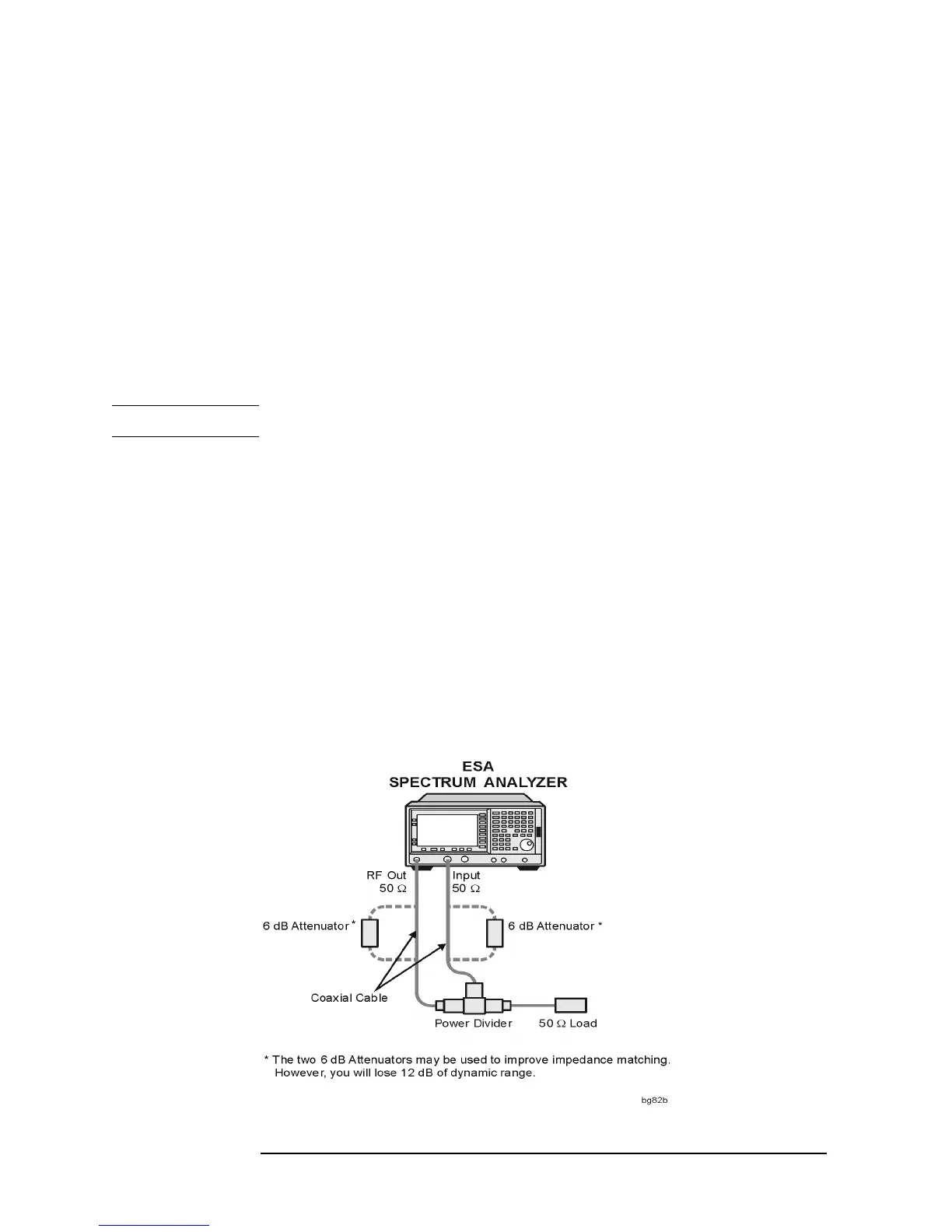
4. Calibrate the spectrum analyzer.
Calibration removes any errors introduced by the cabling and
components of the test setup before making the measurement.
NOTE Press the Esc front panel key to cancel this procedure at any stage.
a. Disconnect the cable to be tested.
b. Press the
Meas Setup front panel key.
c. Press the
Calibrate menu key.
Connect a 50 ohm terminator to the analyzer via the power
divider as prompted (see Figure 5-2).
d. Press the
Calibrate menu key.
e. Re-connect the cable to be tested in place of the load, as prompted
by the dialog box.
f. Press the
Esc front panel key to remove the dialog box and end
the calibration procedure.
Figure 5-2 Calibrating the spectrum analyzer for cable fault location