Maintaining the Instrument
Leak Testing a G1289 to 6890 GC Interface
109
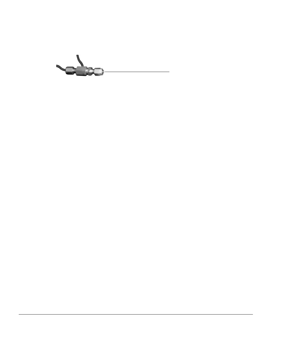
Figure 28. Cap the aux bleed fitting
6. Monitor the pressure on the front panel display—it should equilibrate at
some pressure lower than 20 psi and then hold. The pressure will drop
slightly at first, then stabilize. At this point, it should drop less than 1 psi in
5 minutes. If the unit cannot maintain pressure, there is a leak in the vial
pressurization flow path.
7. Using MANUAL OPERATION, switch the sample valve and repeat steps
2–6. If the unit cannot maintain pressure, there is a leak at the sample tube
fittings.
8. De-pressurize the system by opening the vent valve from MANUAL
OPERATION.
Correcting leaks
1. If the headspace sampler–GC system failed the test, isolate the source of
the leak by using MANUAL OPERATION to toggle the Pressurize Valve to
“OFF.”
2. Repeat steps 4–6 under ““Leak test” on page 108” above.
If the unit passes the test, the leak is in the headspace unit at either the
Vent Valve, the connections on the sampling valve, probe connections, or
vial cap/septum.
If the unit fails the test, the leak is in the Aux control module, the
Swagelok fittings on the back of the sampler, or the auxiliary bleed fitting.
Cap on open end
of fitting
 Loading...